Figure 9-2, Sqm-242 operating manual, Figure 9-2 frequency response spectrum – INFICON SQM-242 Thin Film Deposition Controller Card Operating Manual User Manual
Page 89
9 - 3
IP
N 07
4-
54
9-
P1
A
SQM-242 Operating Manual
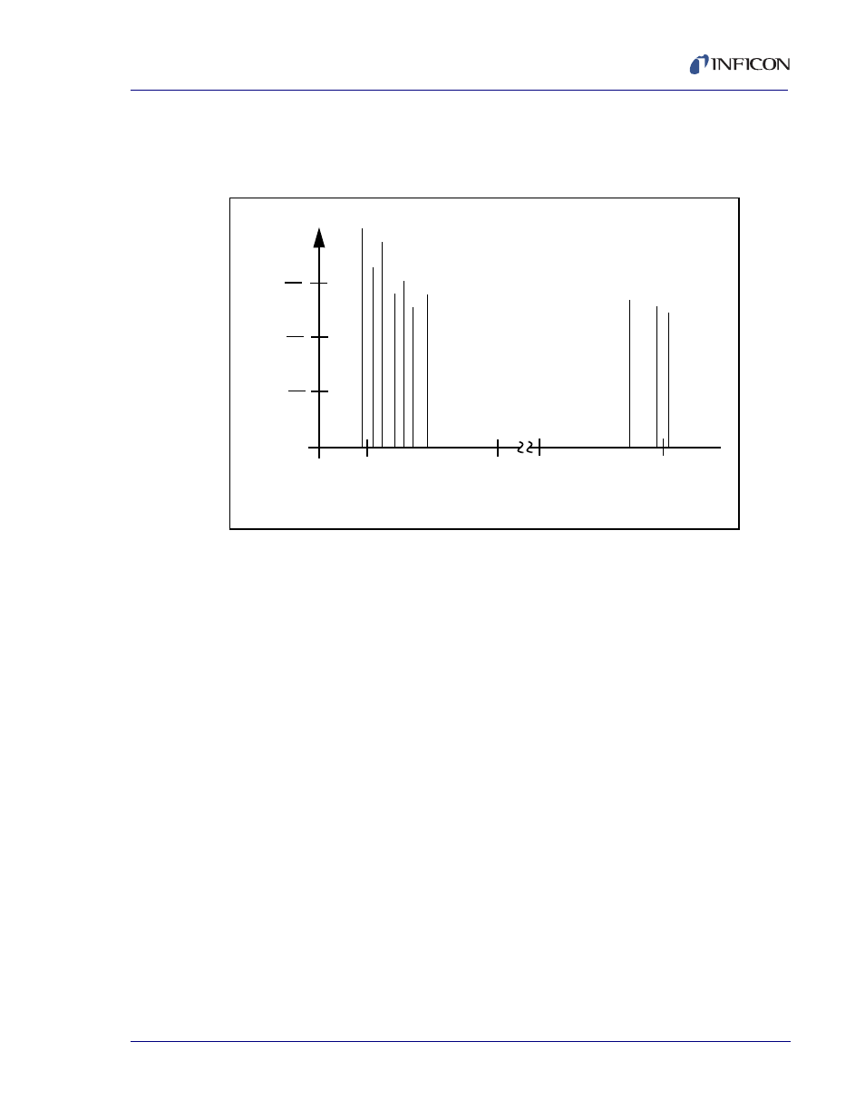
reduces the intensity of response of the generally unwanted anharmonic modes;
hence, the potential for an oscillator to sustain an unwanted oscillation is
substantially reduced.
Figure 9-2 Frequency Response Spectrum
The use of an adhesion layer has improved the electrode-to-quartz bonding,
reducing “rate spikes” caused by micro-tears between the electrode and the quartz
as film stress rises. These micro-tears leave portions of the deposited film
unattached and therefore unable to participate in the oscillation. These free
portions are no longer detected and the wrong thickness consequently inferred.
The “AT” resonator is usually chosen for deposition monitoring because at room
temperature it can be made to exhibit a very small frequency change due to
temperature changes. Since there is presently no way to separate the frequency
change caused by added mass (which is negative) or even the frequency changes
caused by temperature gradients across the crystal or film induced stresses, it is
essential to minimize these temperature-induced changes. It is only in this way that
small changes in mass can be measured accurately.
5.
98
1 M
H
z 1
5 oh
m
6.
15
3 M
H
z 5
0 oh
m
6.
19
4 M
H
z 4
0 oh
m
6.3
33
MH
z 14
2
ohm
6.3
37
MH
z 10
5
ohm
6.3
48
MH
z 32
2
ohm
6.4
19
MH
z 35
0
ohm
17
.7
92
M
H
z 27
8 o
hm
17
.9
57
M
H
z 31
1 o
hm
18
.1
33
M
H
z 35
0 o
hm
Log of
r
e
lat
iv
e
in
te
nsity
(
A
dmit
ta
nce
)
Frequency (in MHz)
1
10
1
100
1
1000
6
7
17
18