INFICON SQM-242 Thin Film Deposition Controller Card Operating Manual User Manual
Page 37
3 - 9
IP
N 07
4-
54
9-
P1
A
SQM-242 Operating Manual
Monitor . . . . . . . . . . . . . . . . . . . . . . Monitor sensors halt deposition when their
Thickness setpoint is reached.
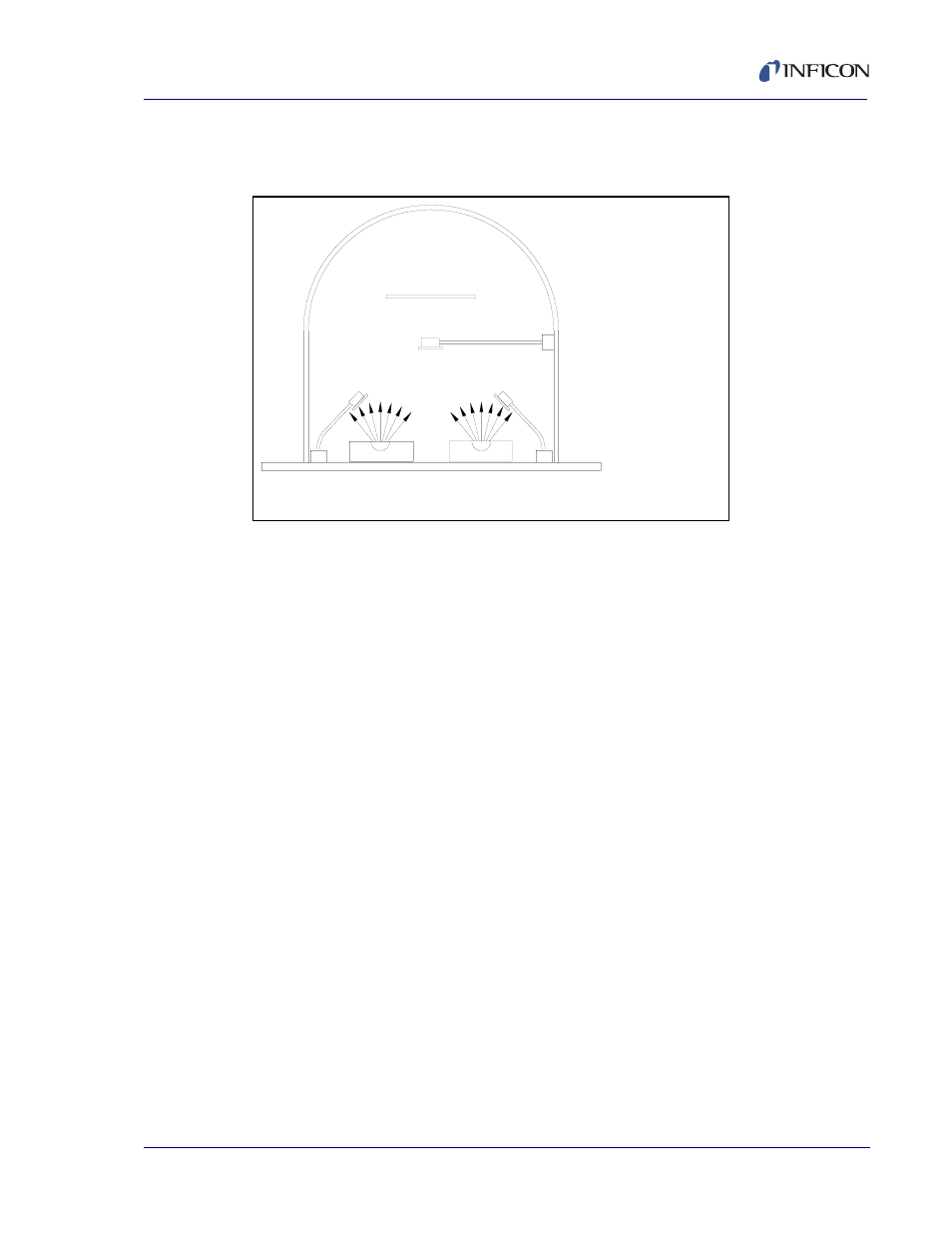
Figure 3-7 Sensor Setup
Often sensors are configured to tightly control the deposition rate of a material,
such as Sensor 1 & 2 above. However, you might also use a monitor sensor near
the substrate, to more accurately monitor the final thickness of the co-deposited
material.
Setpoint . . . . . . . . . . . . . . . . . . . . . . The material thickness (in kÅ) measured by a
monitor sensor that will halt deposition.
Analog . . . . . . . . . . . . . . . . . . . . . . . The SAM-242 analog input card measures
DC voltages in the +/-10 volt range. These
voltages may represent temperature, flow, or
any other process variable. The analog
frame allows you to modify the display to
show values in the desired units, using a
linear (y = mx + b) transformation.
Assume you have a temperature transmitter
that sends 0 V at 0°C and 10 V at 100°C. You
want to control temperature to 200°F (it’s an
example!). Set the analog input Gain to 18,
Offset to 32, and Units to Deg F (F = 9/5C +
32). The SQM-242 will display setpoints and
measurements associated with the analog
input in degrees F.
To leave the analog input display in Volts, set
Gain = 1 and Offset = 0.
Sensor 1 Controls
Material 1 Rate
Sensor 2 Controls
Material 2 Rate
Sensor 3 Monitors
CoDeposited Material