3 the digital valve outputs, The digital valve outputs – INFICON Helium Leak Detector Modul1000 User Manual
Page 97
Technical Data
9-9
jinb
80
e1
-h
Op
er
at
in
g M
a
nua
l
(1
01
1)
9.3
The digital valve outputs
The 16-pin Phönix-connector box is at the back of the device and marked with
"VALVES".
This connector box is used to control external valves.
They can be divided in 2 groups:
1
The pins 13, 14 and 15 are for the connection of a 24 V-valve; maximum
withdrawable current per output 1A. Their common reference point is pin 16 (GND).
2
8 valves can be connected to the contacts 5 to 12. To be more flexible, these
switched outputs are designed to be floating: the user can connect an external direct
voltage source. It must safely be separated from the power supply network and may
apply maximum 30 V.
The 24V-power supply unit of the Modul1000 can be used for supplying the valves.
The valve switches connect to the 24 V-power supply unit on pin 3. Each valve switch
may be loaded with maximum 0.2 A.
Via this pin, the following valves can be controlled by the Modul1000.
*) If control inputs are connected (e.g. valves with integrated electronic circuitry)
instead of solenoid valves, a resistance of 10 kOhm ± 5 % (0.5 W)has to be shunted.
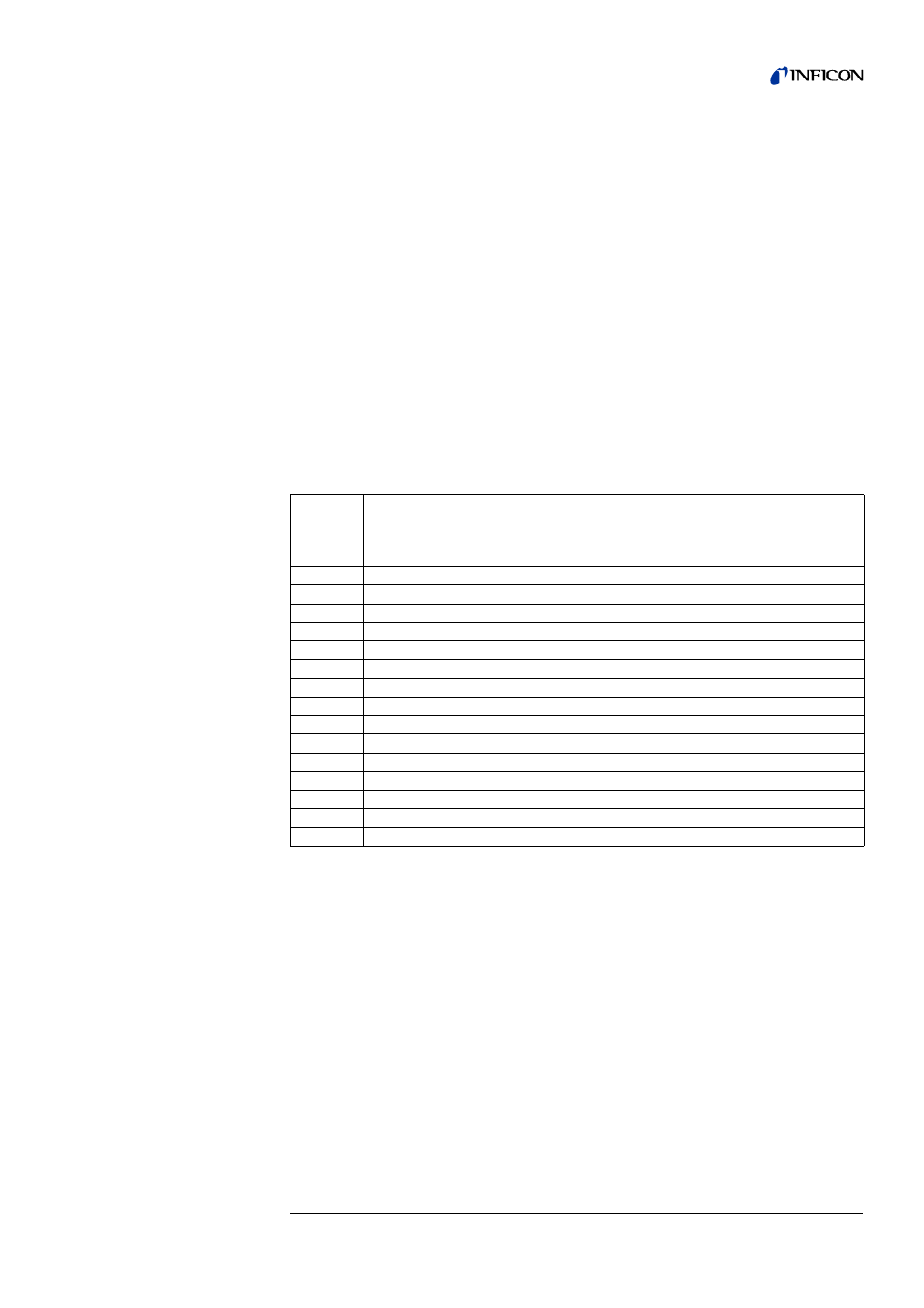
Pin
Assignment
1
24V fuse-protected with F4 (1.6 A) on the interface board. The sum of the
maximum supplied current to this pin and the received current from pin 1 on the
outputs PLC OUT and ACCESSORIES has to be lower than 1.6 A.
2
GND
3
Supply voltage external (24V / 30V max.)
4
Not used - can be used as support pin for the external wiring.
5
Output 1
(V30 Commander mode -evacuate test sample)
6
Output 2
(V31 Commander mode - flood test sample)
7
Output 3
(V32 Commander mode - valve empty test sample)
8
Output 4
(V33 Commander mode - valve fill test sample)
9
Output 5
(V34 Commander mode Emergency valve)
10
Output 6
(V35)
11
Output 7
(V36)
12
Output 8
(V37 external test leak valve 24V / <0,2A)
13
Output 9
(V20 partial flow valve, 24V / <1A) *
)
14
Output 10
(V21 Flooding valve, 24V / <1A) *
)
15
Output 11
(V22 Gas ballast valve, 24V / <1A) *
)
16
GND