7 fuse replacement, 1 overview on electrical fuses, Fuse replacement – INFICON Helium Leak Detector Modul1000 User Manual
Page 82: Overview on electrical fuses
7-10
Maintenance tasks
jinb
80
e1
-h
Op
er
at
in
g M
a
nua
l
(1
01
2)
7.7
Fuse replacement
7.7.1
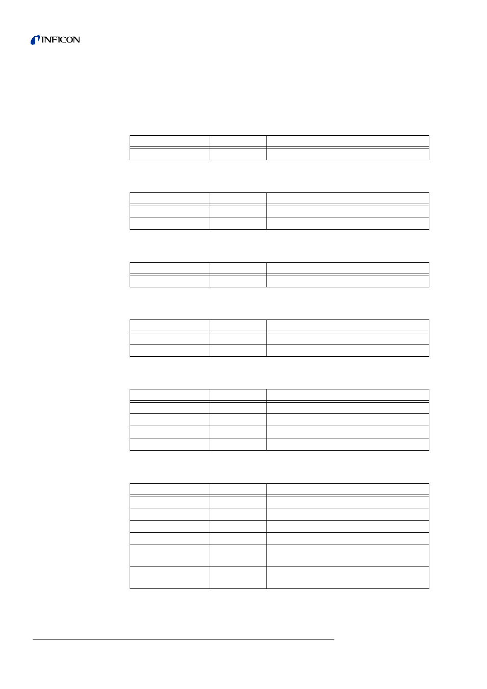
Overview on Electrical Fuses
Notice:
Please note that this work is only performed by skilled electricians, since
generally a cover of an electric module may have to be opened.
Mains switch housing chassis:
Designation
Technical data Fuse for
Mains switch
2 x T 6.3 A
Power supply unit fuse (2-phase OFF)
Wiring plane:
Designation
Technical data Fuse for
F10
T 6,3 A
Power supply unit TC 600
F11
T 0,8 A
Fans
Power supply unit ZWS240PAF-24/TA:
Designation
Technical data Fuse for
F1
F 6.3 A
Fuse power supply unit
I/O PCB:
Designation
Technical data Fuse for
F1; F2
T 0,8 A
not used
F3
T 0,315 A
not used
Circuit board MSV:
Designation
Technical data Fuse for
F1
T 2 A
24 V main fuse for MSV card
F2
T 3,15 A
Anode heater (no use)
F3
T 1 A
15 V; +5V DC/DC transformer
F4
M 0.032 A
Anode- cathode voltage (85 V)
Interface board:
Designation
Technical data
F1
T 1 A
24 V CONTROL UNIT
F2
T 0,8 A
24 V REMOTE CONTROL; PC RS232
F3
T 0,8 A
24 V PRESSURE GAUGE, PLC IN
F4
T 1,6 A
24 V PLC OUT; VALVES; ACESSORIES
F5
T 1,0 A
VALVES V30...V33 supply voltage (max.
30 V)
F6
T 1,0 A
VALVES V34...V37 supply voltage (max.
30 V)