2 control via the plc inputs and outputs, 1 plc inputs, Control via the plc inputs and outputs – INFICON Helium Leak Detector Modul1000 User Manual
Page 91: Plc inputs, Caution
Technical Data
9-3
jinb
80
e1
-h
Op
er
at
in
g M
a
nua
l
(1
01
1)
9.2
Control via the PLC inputs and outputs
If the Modul100 shall be controlled via the PLC inputs and output, select one of the
control location "PLC", "All" or "Local and PLC" (refer to chapter or SB).
9.2.1
PLC inputs
The 14-pin Phönix-connector box is located at the back of the device and is marked
with PLC In / Audio. The pin assignment of the connector box is freely selectable
(Also refer to Interface Description).
The pins are numbered from the left to the right side.
Error or warning messages may occur when the connection cable is disconnected or
connected during operation.
Description of operation mode of the Digital In.
A signal between 0 V and 7 V is recognized to be LOW, a signal >13V is recognized
to be HIGH. The maximum signal level of direct voltage is 30V. All functions are also
selectable as inverted functions.
Notice:
Signals at these inputs are only accepted if the location of control is set to
PLC or Local and PLC.
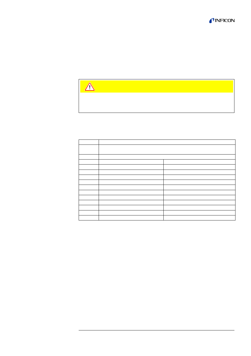
Caution
The electronic system of the Modul1000 may be damaged by too high input
voltages.
The maximum permissible input direct voltage is 30V.
Pin
Assignment
1
24V fuse-protected with F3 on the interface board (0.8 A, maximum output
current, on this pin together with Pin 1 on connection PRESSURE GAUGE)
2
GND
3
Freely configurable PLC input
e.g. START (default setting)
4
Freely configurable PLC input
e.g. STOP (default setting)
5
Freely configurable PLC input
e.g. ZERO (default setting)
6
Freely configurable PLC input
e.g. CAL (default setting)
7
Freely configurable PLC input
e.g. CAL INTERN(default setting)
8
Freely configurable PLC input
e.g. CAL EXTERN (default setting)
9
Freely configurable PLC input
e.g. CLEAR (default setting)
10
Freely configurable PLC input
e.g. GAS BALLAST (default setting)
11
PLC GND (reference potential)
12
free
13
AUDIO_OUT
5V level, PWM-output
14
GND (24 V)