Video balancer – COATS Series XR 1800 Balancer User Manual
Page 28
22 •
Important: Always read and follow the on-screen operating instructions.
Video Balancer
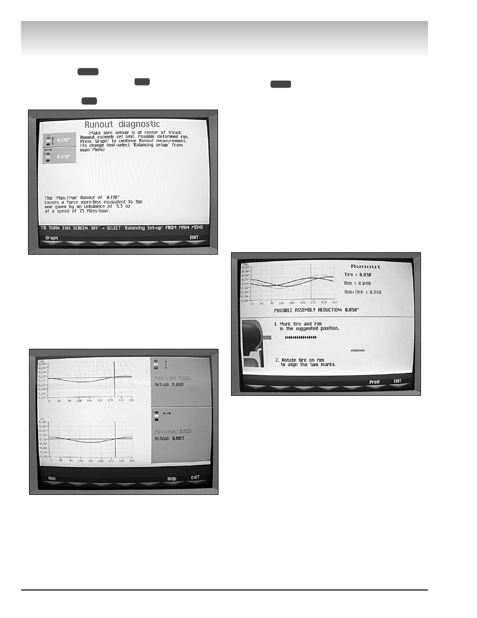
Runout (Runout Match)
Select the
button and then the RUNOUT
(RUNOUT MATCHING) option
or, if the wheel bal-
ancer software is set to automatically detect runout,
select GRAPH
at the Runout Diagnostic screen.
Figure 38 - Select Graph at the Runout Diagnostic Screen
Evaluate runout information at the “graph”
screen, see figure 39. The red curve in the upper
graph is the average radial runout of the assembly
that is how much the runout of the assembly mim-
ics running “off-center”. The red curve in the lower
graph is the average lateral runout of the assembly
and a large number here indicates a bent rim,
deformed sidewall, or both.
Figure 39 - Runout Measurement Screen
1. At the “graph” screen, select Rim to evaluate the
rim verses the tire radial runout. Follow the on-screen
instructions.
2. Touch the rim with the diameter arm.
Note: Place the offset arm, as shown on-screen, just
under the inside of the barrel of the rim and hold in
place. Do not place the offset arm at the clip-on
weight location.
3. Press
and turn the wheel slowly.
Note: Hold the offset arm in place one revolution until
you reach 100%. Your progress is displayed on-screen.
The wheel balancer software calculates and displays
a possible assembly runout reduction in inches based
on the suggested tire on rim positioning. At this point,
based on the possible reduction, choose to continue or
exit the procedure. If the reduction amount does not
exceed the CORRECTION RUNOUT LIMIT setting, the
screen will display “Assembly Cannot Be Corrected by
Matching”.
4. 1. Mark tire and rim in the suggested position.
To mark the tire position, rotate the wheel in the
direction of the black arrows until the red “chalk” icon
appears on the tire. Step on the positioning pedal, then
mark the tire on the outside at top-dead-center.
Figure 40 - “Chalk” Icon to Indicate TDC Tire Position
To mark the rim position, rotate the wheel in the
direction of the blue arrows until the red “chalk” icon
appears on the rim. Step on the positioning pedal, then
mark the rim on the outside at top-dead-center.
5. 2. Rotate tire on rim to align the two marks.
Remove the wheel from the balancer. Using the tire
changer, break down the assembly and position the
tire and rim so that the marks line up. The tire is now
optimized.
Complete by balancing the wheel assembly following
normal procedures.
START
1
2
MENU