COATS Kit 8113900 Monitor Replacement User Manual
Disassembly instructions, Assembly instructions
8113899 00 03/04
© COPYRIGHT 2004 HENNESSY INDUSTRIES AND COATS ALL RIGHTS RESERVED PRINTED IN U.S.A.
XR1800 Monitor Replacement
Kit 8113900
COATS, Inc. • Hennessy Industries • 1601 J.P. Hennessy Drive, LaVergne, TN 37086-3565
(800) 688-6359 • (615) 641-7533 • (615) 641-5104 FAX • www.ammcoats.com
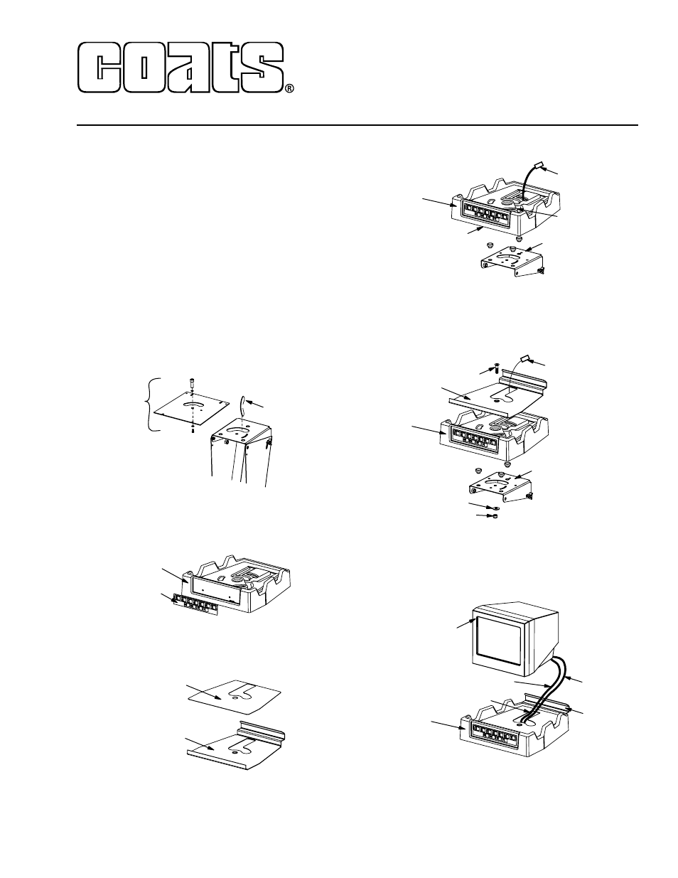
Disassembly Instructions
1. Turn Off power to balancer.
2. Unplug Touch Panel Ribbon Cable and remove
Monitor Housing.
3. Remove Touch Panel and Hardware and save for
installation on new Monitor Tray (8113742).
4. Unplug Monitor Video Cable at Main PCB. Unplug
Monitor Power Cable at Power PCB inside cabinet.
5. Remove Monitor, Monitor Base Plate, Elastic Cord,
and Cables. Set aside to ship back to Hennessy along
with Monitor Housing.
6. Remove and discard red flat Base Plate under mon-
itor (8113271).
7. Remove and discard Grommet in circular slot of
Monitor Tilting Bracket.
Assembly Instructions
1. Assemble Touch Panel (removed from old monitor
housing) to front of new Monitor Tray (8113742).
2. Assemble adhesive backed Grip Strip (8113744) to
Monitor Plate (8113743), as shown.
3. Place Monitor Tray (8113742) on Tilt Bracket, route
Ribbon Cable in groove to Touch Panel and connect
under front edge of Tray. Connect Monitor Power Cable
at Power PCB and route through tower to back of
Monitor Tray.
4. Place Monitor Plate (8113743) with Grip Strip in
Monitor Tray and bolt Plate/Tray to Tilting Bracket using
1/2-13x2 Flat Head Socket Cap Screw with 1/2-inch Flat
Washer and 1/2-13 Nylok Nut under Tilt Bracket. Tighten
until Tray is difficult to move side to side.
5. After feeding Monitor Video Cable through circular
slot in Tray and into Monitor Tower, place Monitor in
Tray. Make sure Monitor Cables fit in slot under Monitor
at back of Tray and in channel at back of Monitor Plate.
Connect Monitor Power Cord at back of Monitor.
6. Connect Video Cable at Main PCB. Tie cables in
tower and main cabinet as required.
7. Power up machine. Turn On Monitor and adjust
screen as required.
Discard Grommet
Discard
Base Plate
Grip Strip
Monitor Plate
Touch Panel
and Monitor Tray
Tilt Bracket
1/2" Washer
1/2-13 Nylok Nut
1/2-13 x 2"
Monitor
Power Cable
Monitor Plate
Monitor Tray
Touch Panel
Touch Panel
and Monitor Tray
Tilt Bracket
Connect Under Here
Groove for
Ribbon Cable
Monitor
Power Cable
Monitor
Touch Panel
and Monitor Tray
Video Cable
Monitor
Power Cable
Slot for Cables
Channel
for Cables