3 component repair and replacement – CHAMPION USN10 User Manual
Page 58
40
5.3 Component Repair and Replacement
(Cont.)
5.3.11 Steam Solenoid Valve Repair
(Cont.)
The 3/4" valves are controlled by a tank heat thermostat, (See 5.3.8), which connects 120VAC
to the valve coil during a call for heat. If the valve fails to operate, first check that 120VAC is
supplied to the valve coil. If voltage is not present, then refer to the electrical schematic and
troubleshoot the circuit. If voltage is present then the valve may require a rebuild kit or replace-
ment coil. Turn off power at the dishwasher power switch and main disconnect. Turn
off main incoming steam supply and bleed off any steam pressure in the line. Check the coil for
continuity with a VOM set at the highest resistance range. If the coil checks good then disas-
semble the valve by unscrewing the threaded bonnet with a strap or spanner wrench. Remove
and inspect the valve piston and diaphragm. Inspect the valve seat for mineral deposits and
pitting. (Replace the complete valve assembly if pitting is severe). Reassemble the valve in
reverse order. Turn on steam and power supplies and check for leaks.
The 3/4" valve is controlled by the final rinse control thermostat, (See 5.3.10), which connects
120VAC to the valve coil during a call for heat. If the valve fails to operate, first check that
120VAC is supplied to the valve coil. If voltage is not present, then refer to the electrical sche-
matic and troubleshoot the circuit. If voltage is present then the valve may require a rebuild kit or
replacement coil. Turn off power at the dishwasher power switch and main disconnect. Turn off
main incoming steam supply and bleed off any steam pressure in the line. Check the coil for
continuity with a VOM set at the highest resistance range. If the coil checks good then disas-
semble the valve by removing the four bolts in the valve bonnet. Remove and inspect the valve
piston and diaphragm. Inspect the valve seat for mineral deposits and pitting. (Replace the
complete valve assembly if pitting is severe). Reassemble the valve in reverse order. Turn on
steam and power supplies and check for leaks.
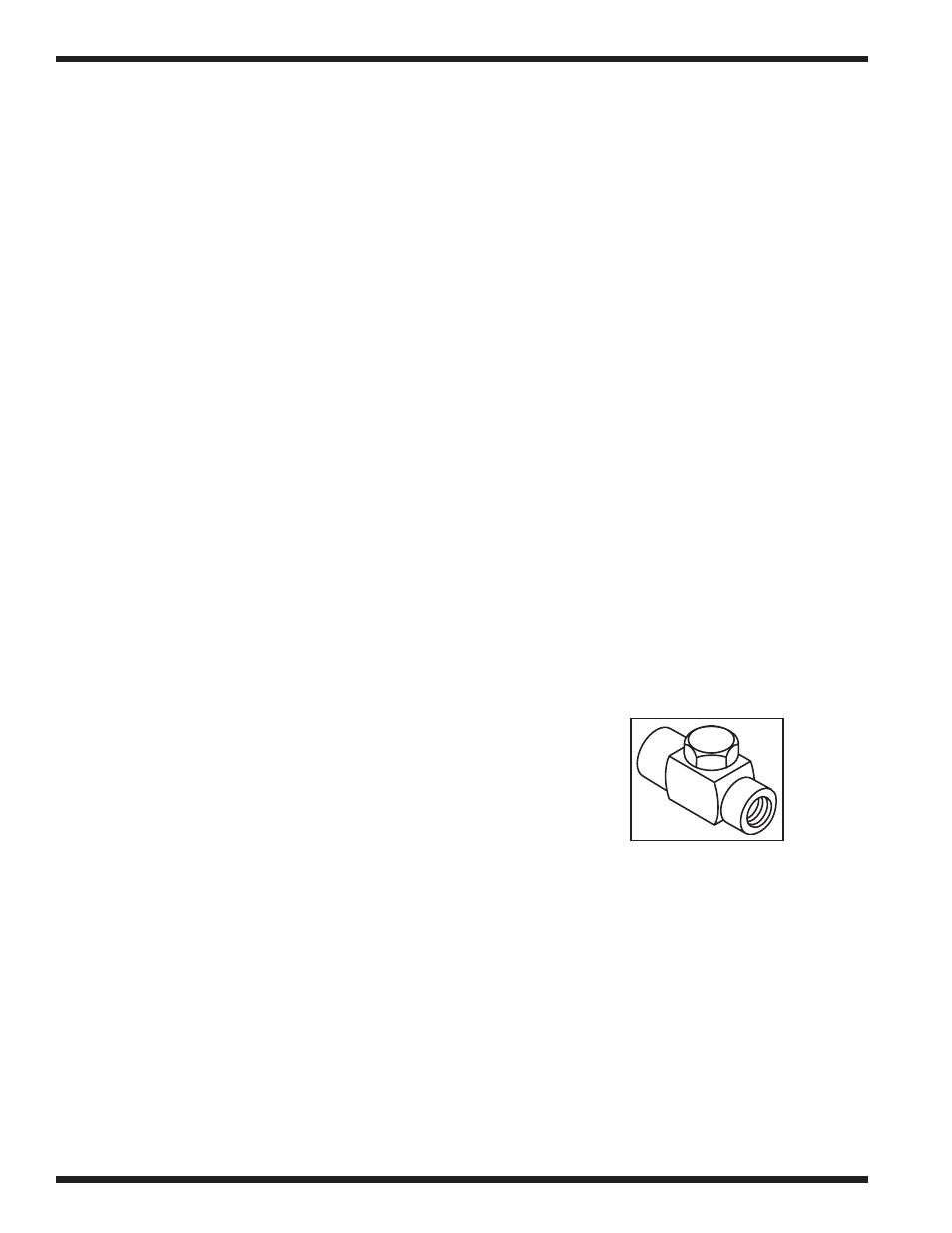
5.3.12 Steam Trap Repair and Replacement
1/2" NPT thermodynamic steam traps are installed in the condensate lines
for the steam booster and tank heat steam coils. All condensate lines for
the USN-10 must be gravity drain with no back pressure in order for the
steam trap to function correctly.
To test the operation of a steam trap: Turn off the steam and water
supplies. Turn off the power at the dishwasher control cabinet. Bleed any steam pressure from
the lines. Disconnect the condensate return line downstream from the steam trap. Return the
dishwasher to normal operation and observe the discharge coming from the steam trap. If you do
not observe small amounts of water periodically discharged then the stream trap is most likely
defective.
To clean a steam trap: Turn off the steam and water supplies. Turn off the power at the dish-
washer control cabinet. Bleed any steam pressure from the lines. Remove the large hex cap in
the center of the steam trap. Remove the disc and inspect the steam trap orifice below.
Clean the orifice with a paper clip or other smooth tool. Reassemble the trap in reverse order.
To replace a steam trap: Turn off the steam and water supplies. Turn off the power at the
dishwasher control cabinet. Bleed any steam pressure from the lines. Break the union in the
condensate line before the steam trap. Remove the trap. Install a replacement trap in reverse
order making sure to apply pipe sealant to threads. Return the dishwasher to normal operation
and test the trap as described above.
PART 5:
BASIC SERVICE