3 service brake, 4 electronic throttle pedal, Service brake – JLG 4017RS Service Manual User Manual
Page 89: Electronic throttle pedal
4-5
3614RS, 4017RS
Cab
4.3.3
Service Brake
a.
Brake Valve Removal
Refer to Section 8.9.2, “Service Brake Valve,” for removal
information.
b. Brake Valve Installation
Refer to Section 8.9.2, “Service Brake Valve,” for installation
information.
4.3.4
Electronic Throttle Pedal
a.
Throttle Pedal Removal
1. Park machine on a firm, level surface, level machine fully
retract boom, lower boom, place transmission in (N)
NEUTRAL, engage park brake and shut engine OFF.
2. Place a Do Not Operate Tag on both ignition key switch
and steering wheel.
3. Open engine covers. Allow system fluids to cool.
4. Properly disconnect battery.
5. Remove access covers from front of cab.
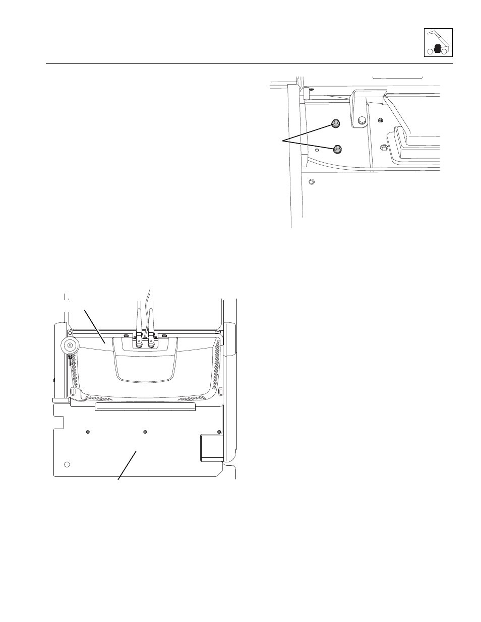
6. Remove hardware (7) securing pedal assembly.
7. Disconnect electrical connection to pedal assembly.
8. Remove throttle pedal assembly from cab.
b. Throttle Pedal Installation
1. Position throttle pedal in its mounting location in cab.
2. Reconnect electrical connection to pedal assembly.
3. Secure throttle pedal into position with previously used
hardware (7).
4. Install protective covers.
5. Properly connect battery.
6. Close and secure engine cover.
7. Remove Do Not Operate Tag from ignition key switch
and the steering wheel.
M 7770
Z
UPPER COVER
LOWER COVER
M 7790
Z
7