11 complete boom installation, Complete boom installation -28 – JLG 4017RS Service Manual User Manual
Page 68
Boom
3-28
3614RS, 4017RS
Note: Grease Tilt cylinder barrel end bore and pin before
installing.
12. Remove the plugs from the fittings on the Tilt cylinder
and the caps from the Tilt hoses from the hose carrier.
Install both Tilt hoses (23). Torque as required.
13. If equipped, remove the plugs from the Auxiliary fittings
and the caps from the Auxiliary hoses from the hose
carrier. Install both Auxiliary hoses (24). Torque as
required.
14. Attach a sling around a balance point on the Extend/
Retract cylinder (25) and carefully set on top of the first
boom section.
Note: Grease Extend/Retract cylinder barrel end bore and rod
end bore and pins before installing.
15. Align the Extend/Retract cylinder barrel end (26) with
bore at rear of the first boom section. Install the pin and
retaining clip (27).
16. Align the Extend/Retract cylinder rod end with bore at
front of the second boom section. Install the pin and
retaining clip (28).
17. Install Extend/Retract cylinder support (29). Torque as
required.
18. Uncap and connect the previously labeled extend/
retract cylinder hoses (30) to the extend/retract
cylinder.
Note: Torque extend and retract chains lock/jam nuts to 115-
125Nm (85-92 lb-ft).
3.10.11
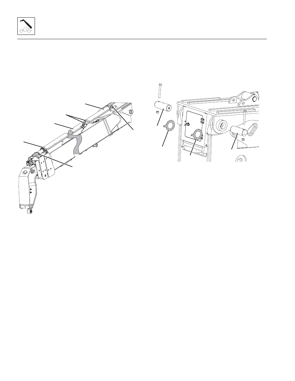
Complete Boom Installation
1. Park the machine on a hard, level surface, place the
transmission in (N) NEUTRAL, engage the park brake
and shut the engine OFF.
2. Place a Do Not Operate Tag on both the ignition key
switch and the steering wheel.
3. Using suitable slings, balance the boom assembly, lift
and carefully guide the boom into place. Align the
frame pivot bores with the boom assembly pivot bores.
Install shims, boom pivot pins and lock bolt (31).
4. With the sling still in place, install the compensating
cylinder, pin and lock bolts.
5. With the sling still in place, install the rod end of the lift/
lower cylinder, pin and lock bolt.
Note: Raising the boom up or down with the sling may be
necessary so the boom, compensating and lift/lower cylinder
bores can be aligned for easier pin installation.
6. Uncap and connect the previously labeled extend/
retract cylinder hoses to the extend/retract cylinder.
7. Uncap and connect the previously labeled tilt hoses and
(if equipped) auxiliary hoses to the appropriate cylinder.
8. Install the boom angle sensor arm. Refer to Section
9. Remove slings and/or supports from the boom
assembly.
10. Start the engine and operate all boom functions several
times to bleed any air out of the hydraulic system. Check
for fluid leaks. Check the hydraulic fluid level in the tank
and add fluid as required.
11. Lower the boom assembly and shut engine OFF.
12. Clean up all debris, hydraulic fluid, etc., in, on, near and
around the machine.
MZ7270
27
30
29
28
25
26
M 7590
Z
31
31
31
31