11 hose carrier assembly, 1 hose carrier removal, 2 hose carrier installation – JLG 4017RS Service Manual User Manual
Page 69: 1 tilt/auxiliary hose removal, Hose carrier assembly, Hose carrier removal, Hose carrier installation, Tilt/auxiliary hose removal
3-29
3614RS, 4017RS
Boom
3.11
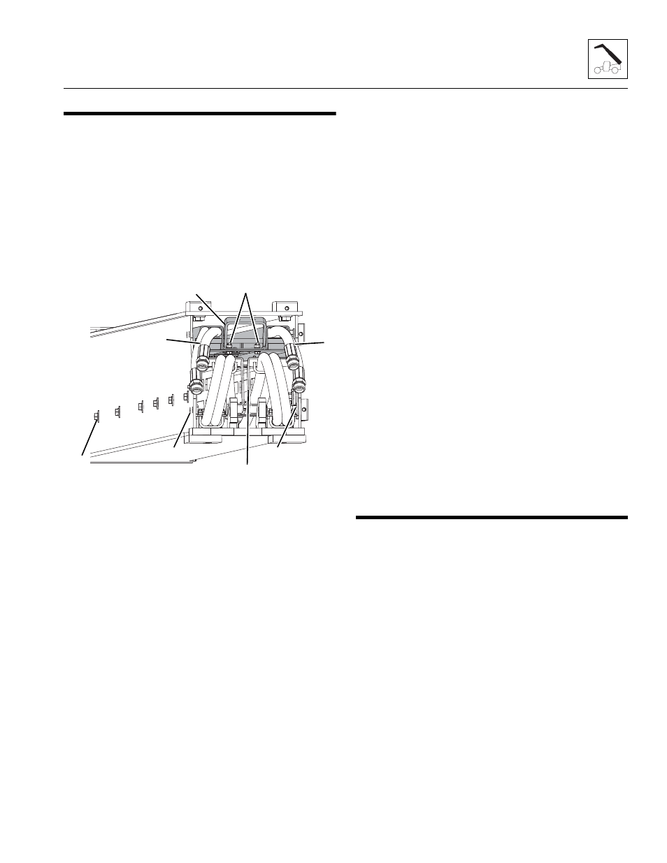
HOSE CARRIER ASSEMBLY
Note: Removal and installation of the hose carrier can also be
performed by removing only the fourth boom section if
required.
3.11.1
Hose Carrier Removal
1. Refer to Section 3.10.4, “Fourth Boom Section
Removal,”for detailed removal instructions.
2. Set the forth boom section on level ground, reposition
the slings and slowly turn the boom section over.
Reposition the slings and set the boom section on
suitable supports.
3. Loosen and remove the two bolts (1) securing the hose
carrier tray (2).
4. Pull the tray (2) from the rear of the fourth boom
section.
5. With fourth boom section setting on suitable supports
loosen and remove the each bolt (3) securing the tilt
hoses and (if equipped) both auxiliary hoses brackets at
the rear of the fourth boom section.
6. Loosen and remove the twelve bolts (six per side)(4) on
the fourth boom section.
7. Pull the hose carrier (5) halfway out of fourth boom
section by hand and set on a suitable support. Place a
sling around the center of the hose carrier to be able to
balance the hose carrier while being removed.
8. Carefully slide the hose carrier (5) the remainder of the
way out of the fourth boom section and set down on
suitable supports.
9. Secure the tilt hoses (and if equipped) the auxiliary
hoses with nylon ties. Remove tilt and/or auxiliary hoses
if required.
3.11.2
Hose Carrier Installation
1. Place a sling around the center of the hose carrier to be
able to balance the hose carrier while being installed.
2. Carefully slide the hose carrier (5) halfway into the
fourth boom section.
3. Remove the sling and push the hose carrier assembly
the remainder of way into the fourth boom section.
4. Apply Loctite
®
243
TM
to the previously removed
mounting bolts.
5. Install the twelve bolts (six per side)(4) on the fourth
boom section.
6. Install the mounting bolts (3) securing the tilt hoses and
(if equipped) both auxiliary hoses brackets at the rear of
the fourth boom section.
7. Insert the tilt hoses (6)(and if equipped) auxiliary hoses
(7) into the hose carrier tray (2).
8. Install the hose carrier tray (2) into the fourth boom
section and secure the hose carrier tray with mounting
bolts (1).
9. Using slings, slowly turn the boom section over.
Reposition the slings and set the boom section on
suitable supports.
10. Refer to Section 3.10.8, “Fourth Boom Section
Installation,” for detailed installation instructions.
3.12
BOTTOM TILT AND AUXILIARY CIRCUIT
HOSE REMOVAL/INSTALLATION -
4017RS
3.12.1
Tilt/Auxiliary Hose Removal
The following procedures can be performed without
disassembling the boom assembly.
1. Remove any attachment from the quick coupler
assembly. Refer to Operation & Safety Manual.
2. Remove the quick coupler assembly. Refer to Section
3.17.1, “Quick Coupler Removal.”
3. Park the machine on a hard, level surface, fully retract
the boom, raise the boom assembly to access lift/lower
cylinder pin and the compensation cylinder pin, place
the transmission in (N) NEUTRAL, engage the park brake
and shut the engine OFF.
4. Place a Do Not Operate Tag on both the ignition key
switch and the steering wheel.
5. Open the engine cover. Allow the system fluids to cool.
6. Properly disconnect the battery.
M 7371
Z
4
3
2
5
1
3
6
7