17 quick coupler, 1 quick coupler removal, 2 quick coupler installation – JLG 4017RS Service Manual User Manual
Page 78: Quick coupler, Quick coupler removal, Quick coupler installation, Section, 1, “quick coupler removal
Boom
3-38
3614RS, 4017RS
each side.
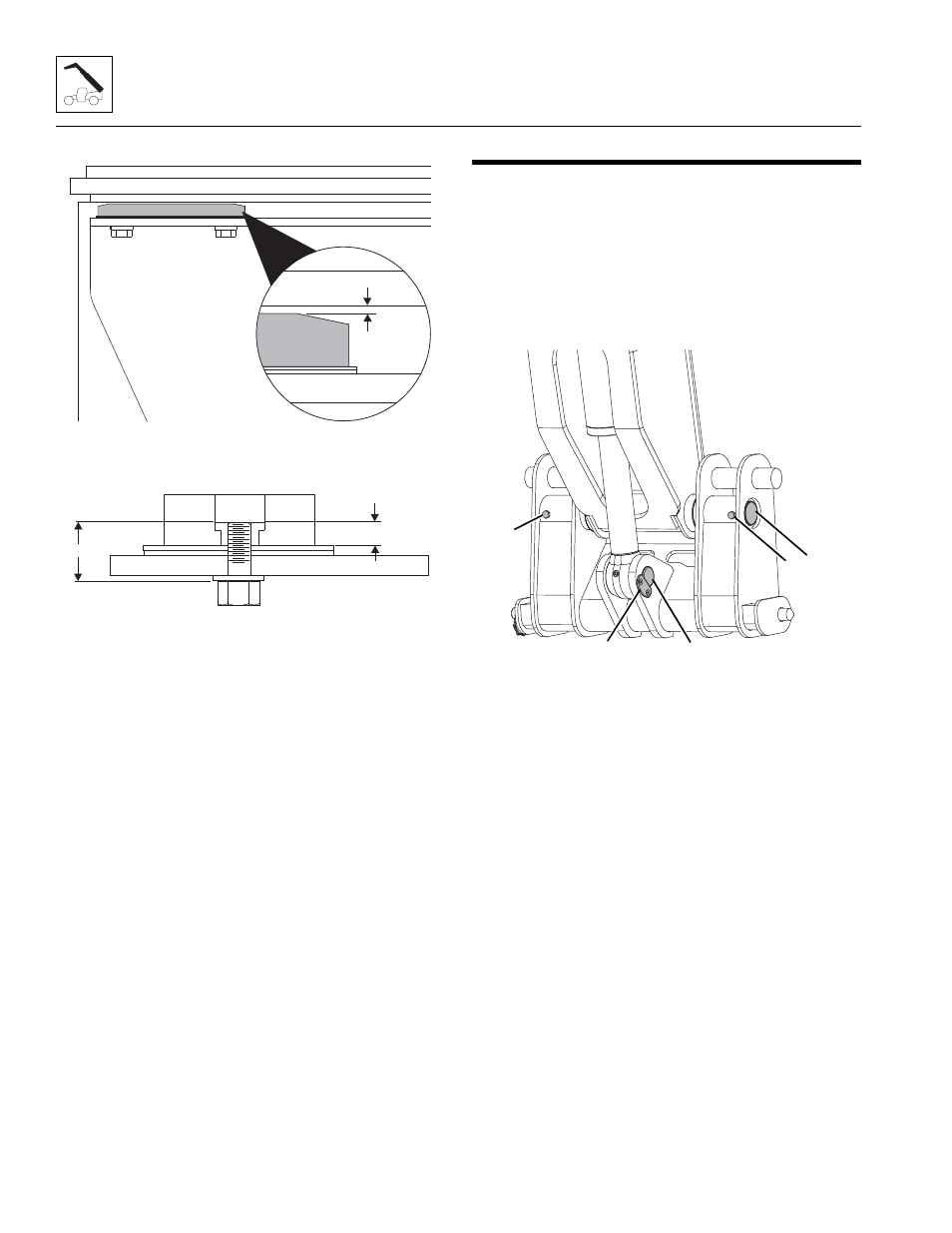
• Maintain a total boom section clearance of
0,5-1,5mm (0.020 to 0.060 in) between the wear pad
and the next boom section (5).
• The length of the wear pad bolt depends on the
number of shims, spacers and washers being used.
• The thickness of each threaded wear pad insert is 10mm
(0.393 in) (A).
• The bolt length should be determined by measuring
the distance from the face of the insert to the face of the
boom (B) including any spacer, shim(s) and washer(s).
• Bolt thread engagement in the wear pad insert should
not extend.
• One or two hardened washers are to be used on each
wear pad bolt except where noted otherwise.
DO NOT use more than two hardened washers.
• Use only one hardened washer if mounting bolts are
recessed.
• Wear Pad Bolt Torque:
M12 x 20, 95-105Nm - M12 x 25, 95-105Nm
M12 x 30, 95-105Nm - M12 x 35, 95-105Nm
M12 x 40, 95-105Nm - M12 x 80, 95-105Nm
• Lubricate the face and pockets of each wear pad after
being installed.
Boom Section Wear Pad Pathway Lubrication:
• Clean and lightly grease all wear pad pathways with
Multipurpose Grease.
• Clean and lightly grease the hose carrier guide bar
pathway with Multipurpose Grease.
3.17
QUICK COUPLER
Note: The following procedures covers all styles of quick
couplers.
3.17.1
Quick Coupler Removal
1. Lower attachment to ground, tilt forward to access
coupler pin, set park brake and turn off engine.
2. If equipped with a hydraulic quick coupler device, refer
to Operation & Safety Manual.
3. Remove the bolts and lock bracket (6) holding the rod
end tilt cylinder pin to the quick coupler assembly.
Remove the rod end pin (7).
4. Support the quick coupler assembly. Remove the bolts
(8) and pin (9) from the quick coupler assembly.
5. Inspect the above pins for nicks or surface corrosion.
Use fine emery cloth to fix minor nicks or corrosion. If
damaged or if it cannot be repaired the pin must be
replaced.
3.17.2
Quick Coupler Installation
1. Apply Loctite
®
243
TM
to all mounting bolts.
2. Assemble the quick coupler to the boom head. Line up
the quick coupler between the mounts on the boom
head. The quick coupler should be centered in the
boom head.
3. Coat the quick coupler pivot pin with Anti-Seize Lube.
Insert the quick coupler pivot pin (9) through the quick
coupler and boom head. Secure with the previously
removed bolts (8).
4. Align the quick coupler with the rod end tilt cylinder
and insert the coupler pin (7) and replace the lock
bracket and bolt assembly (6).
MZ7660
5
MY3620
A
B
MZ7690
6
8
7
8
9