9 control valves, 1 main control valve, Control valves – JLG 4017RS Service Manual User Manual
Page 141: Main control valve
8-11
3614RS, 4017RS
Hydraulic System
8.9
CONTROL VALVES
8.9.1
Main Control Valve
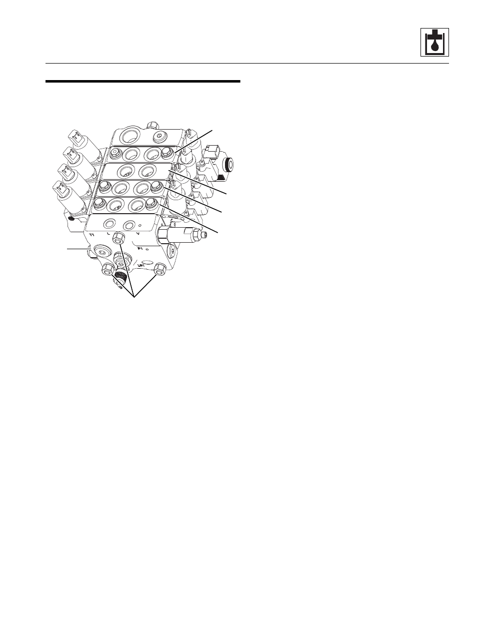
The main control valve is mounted at the rear of the cab.
The main control valve assembly (1) consists of working
sections with their own valve assemblies, each providing a
specific hydraulic function. Those functions are:
lift/lower (2), extend/retract (3), tilt (4) and auxiliary (5).
a.
Main Control Valve Removal
1. Park the machine on a firm, level surface, level the
machine, fully retract the boom, lower the boom, place
the transmission in (N) NEUTRAL, engage the park brake
and shut the engine OFF.
2. Place a Do Not Operate Tag on both the ignition key
switch and the steering wheel.
3. Open the engine cover. Allow the system fluids to cool.
4. Properly disconnect the battery.
5. Remove the main control valve cover.
6. Thoroughly clean the main control valve and
surrounding area, including all hoses and fittings,
before proceeding.
7. Place a suitable container to catch hydraulic fluid
drainage beneath the cab.
8. Drain the hydraulic oil reservoir. Refer to Section 8.7.1,
“Hydraulic Oil Reservoir Draining.”
9. Label, disconnect and cap all the hydraulic hoses, tubes
and wires at the main control valve. Slowly turn hose
fittings to allow any trapped pressure in the hydraulic
system to escape.
10. Wipe up any hydraulic fluid spillage in, on, near and
around the machine and the work area.
11. Support the valve and remove the four bolts securing
the main control valve to the frame. Remove the main
control valve.
b. Main Control Valve Disassembly
1. To disassemble the individual sections of the main
control valve, remove the nuts from one end of the tie
rods.
2. Disassemble each section assembly as required.
Some sections include a pre-adjusted relief valve that
regulates pressure in a specific circuit.
Note: DO NOT adjust any of the relief valve assemblies.
Tampering with a relief valve will irrevocably alter pressure in the
affected circuit, requiring recalibration or a new relief valve.
Disassemble each Valve Section
1. Carefully separate the load sense outlet section (5) from the
next section.
2. Remove the o-rings from between the two sections.
3. Carefully separate each remaining section.
4. Remove any check valves, compensator valves, anti-
cavitation valves or shock valves from individual valve
section if equipped.
5. Keep all parts being removed from individual valve
sections tagged and kept together.
c.
Main Control Valve Parts Cleaning
Clean all components with a suitable cleaner, such as
triclorethylene, before continuing. Blow dry.
d. Main Control Valve Parts Inspection
Inspect all parts and internal passageways for wear, damage,
etc. If inner surfaces of any component DO NOT display an
ultra-smooth, polished finish, or are damaged in any way,
replace the damaged part. Often, dirty hydraulic fluid causes
failure of internal seals, damage to the polished surfaces
within the component, and wear of and/or harm to other
parts.
M 8060
Z
2
3
4
5
1
6