JLG 4017RS Service Manual User Manual
Page 178
Electrical System
9-26
3614RS, 4017RS
3. Place a Do Not Operate Tag on both the ignition key
switch and the steering wheel, stating that the machine
should not be operated.
4. Open the engine cover. Allow the engine to cool.
5. Properly disconnect the battery.
6. Disconnect the LSI electrical connector.
7. Loosen, remove and discard the two bolts holding the
LSI assembly to the rear axle.
8. Remove and discard the sensor assembly.
b. LSI Sensor Installation
1. Ensure threads of both bolt holes are clean and free
from rust, water and debris.
2. Clean the bare metal with a degreasing agent, Loctite
®
7063.
3. Remove any excess degreasing agent and allow to dry.
4. Apply a thin film of Loctite
®
Initiator #1 (may also be
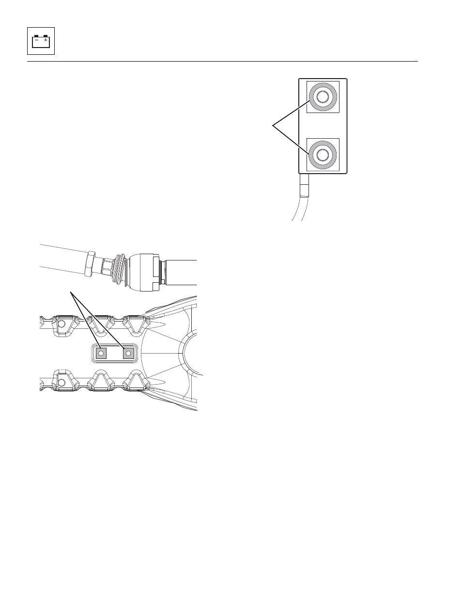
denoted as Initiator #5) activator approximately 6 cm² (1
in²) to the two flat metal surfaces (8) of the sensor,
ensuring the adhesive is spread evenly over the entire
surface.
Note: Follow all adhesive manufacturer’s recommendations
including storage life.
5. Apply an 3mm (0.125 in) bead of Loctite
®
A2460
Adhesive to each metallic mounting pad (9) on the
sensor. The bead should center on the mounting hole
and be equally spaced between the hole and the edge
of the mounting pad as shown above.
6. Do Not spread the bead prior to mounting the sensor.
7. Fit the sensor, ensuring the lead exits in the corner
direction. Secure with two new bolts - Socket HD
Capscrew M10x35x1.5, Grade 12.9.
Note: It is important to prevent distortion of the sensor
element, therefore tighten each bolt finger tight. Alternately
tighten each bolt to 35 Nm (26 lb-ft) and finally to 70-80 Nm
(52-59 lb-ft).
8. Permanently mark position of bolt head and sensor
body.
9. Apply a thin bead of sealant around the perimeter of
the sensor.
10. Leave the machine undisturbed for a minimum of 1
hours before moving.
11. Plug the electrical connector into the sensor assembly.
12. Properly connect the battery.
13. Close and secure the engine cover.
14. Remove the Do Not Operate Tag from the ignition key
switch and the steering wheel.
15. Drive the machine over speed bumps or similar
obstacles to exercise the epoxy bond.
16. Calibrate the LSI system, refer to Section 9.10.3, “LSI
M 8240
Z
8
MZ8250
9