2 steering column/orbitrol valve, Steering column/orbitrol valve – JLG 4017RS Service Manual User Manual
Page 88
Cab
4-4
3614RS, 4017RS
4.3.2
Steering Column/Orbitrol Valve
a.
Steering Column and Orbitrol Valve Removal
1. Park machine on a firm, level surface, level machine fully
retract boom, lower boom, place transmission in (N)
NEUTRAL, engage park brake and shut engine OFF.
2. Place a Do Not Operate Tag on both ignition key switch
and steering wheel.
3. Open engine cover. Allow system fluids to cool.
4. Properly disconnect battery.
5. Remove lower dash panel in cab.
6. Remove access covers from front of cab.
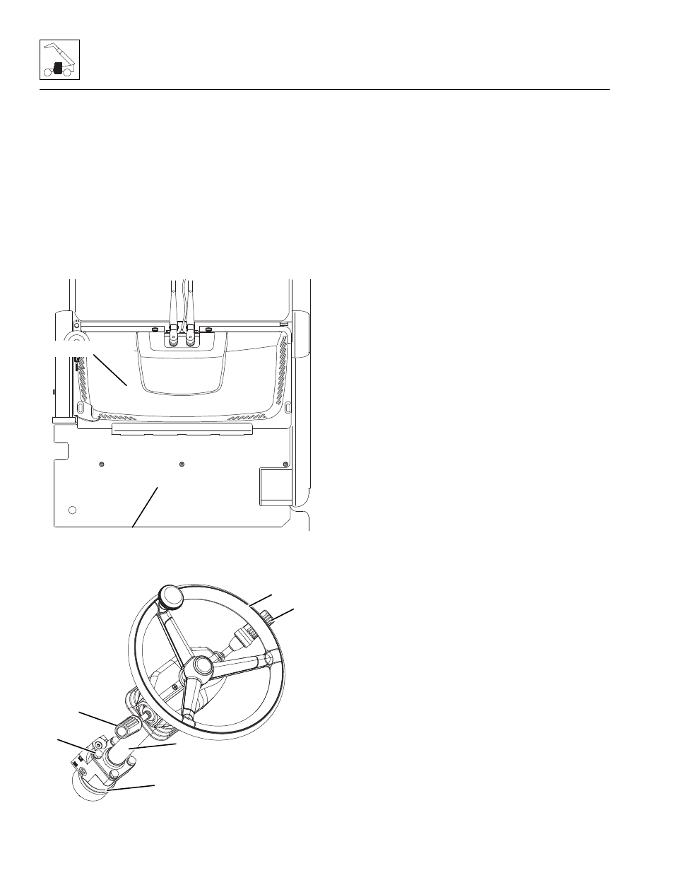
7. Label, disconnect and cap hydraulic hoses attached to
orbitrol valve (1).
8. Remove steering wheel (2). Refer to Section 4.3.1,
9. Disconnect and remove the accessory control lever (3),
and if equipped, transmission control lever (4).
Disconnect control lever(s) harness from the main cab
harness.
10. Have an assistant hold the orbitrol valve from outside of
cab. Remove bolts (5) securing orbitrol valve to cab.
11. Remove the steering column (6) through the dash panel
opening.
Note: DO NOT disassemble orbitrol valve. The orbitrol valve is
not serviceable and must be replaced in its entirety, if defective.
b. Steering Column and Orbitrol Valve Installation
1. Install steering column to original orientation in cab.
2. Have an assistant hold orbitrol valve in original
orientation from outside cab. Install steering column to
valve with previously removed hardware.
3. Install accessory control lever, and if equipped,
transmission control lever. Connect control lever(s)
harness connector to main cab harness and install steering
wheel assembly.
4. Uncap and connect previously labeled hydraulic hoses
to orbitrol valve.
5. Carefully examine all connections one last time before
engine start-up. Rectify any faulty conditions.
6. Properly connect battery.
7. Start engine and check operation of steering system.
Check for hydraulic fluid leaks. Check hydraulic fluid
level in tank and add fluid as required.
8. Install access covers to front of cab.
9. Install lower dash panel in cab.
10. Close and secure engine cover.
11. Remove Do Not Operate Tag from ignition key switch
and steering wheel.
c.
Steering Test
Conduct a pressure check of the steering hydraulic circuits at
the main control valve. Refer to Section 8.4.1, “Pressure
Checks and Adjustments.”
M 7770
Z
UPPER COVER
LOWER COVER
MAM3930
1
2
4
3
5
6