18 forks, 19 boom prop (if equipped), 1 installation and removal procedures – JLG 4017RS Service Manual User Manual
Page 79: Forks, Boom prop (if equipped), Installation and removal procedures, Warning
3-39
3614RS, 4017RS
Boom
5. If equipped, reconnect the hydraulic attachment hoses
to the quick disconnect fittings on the left side of the
boom head.
3.18
FORKS
Forks should be cleaned and inspected prior to being
attached to carriage. If the following criteria is not met, forks
must be removed from service immediately.
Daily Inspection
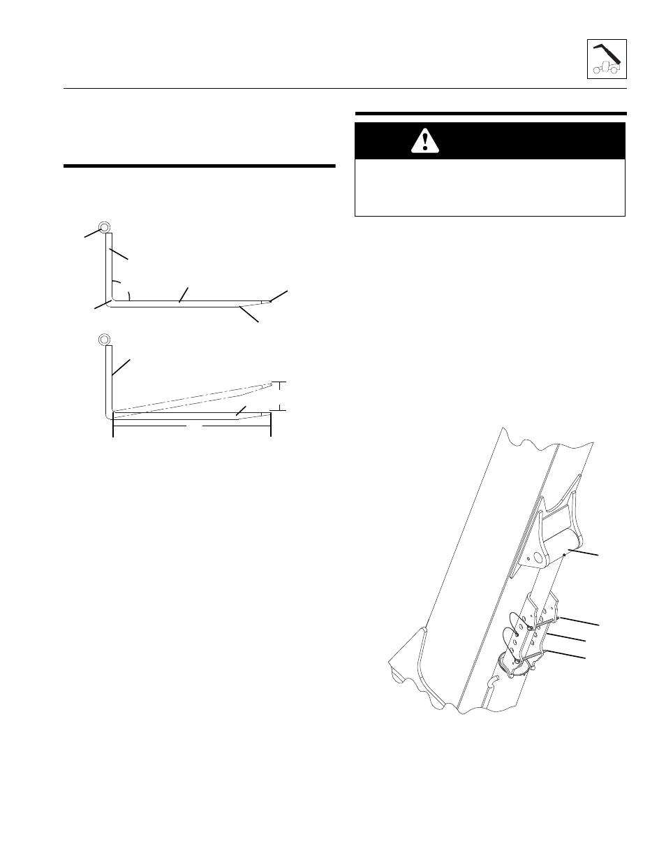
1. Inspect forks (10) for cracks, paying special attention to
heel (11) and mounting tubes (12).
2. Inspect forks for broken or bent tips (13) and twisted
blades (14) and shanks (15).
Yearly Inspection
1. Straightness of the upper face of blade (14) and the
front face of shank (15) should not exceed 0.5 percent of
the length of blade or height of shank.
2. Angle (16) between upper face of blade and front face
of shank should not exceed 93 degrees.
3. Thickness of blade (14) and shank (15) should not be
reduced to 90 percent of original thickness.
Note: Contact the local JLG dealer with the fork part number to
find the manufactured dimensions of the fork blade.
4. Ensure fork length (17) is adequate for intended loads.
5. Fork markings should be legible, re-stamp if required.
6. Compare fork tips (18) when mounted on a carriage.
Maximum difference in height of fork tips is 3 percent of
the length of the blade (17).
3.19
BOOM PROP (IF EQUIPPED)
3.19.1
Installation and Removal Procedures
a.
Prop Installation
1. Park the machine on a firm, level surface. Place the
transmission in (N) NEUTRAL, engage the park brake
switch.
2. Raise the boom to an angle of approximately 20
degrees. Stop engine.
3. Place a Do Not Operate Tag on both the ignition key
switch and the steering wheel.
4. Before installing the boom prop, inspect the prop for
damage. Do not use if the prop is damaged or if the
locking pins are damaged or missing.
5. Align lift cylinder prop (19) so the locking pins (20) are
on the bottom side of the lift/lower cylinder rod (21).
Install the boom prop (19) onto the lift/lower cylinder
(19). Install locking pins (20).
MH6460
12
11
15
16
14
10
13
15
14
17
18
WARNING
A raised boom can fall if a hydraulic component is
removed. Remove any load, retract the boom and install
the boom prop or a suitable supporting stand before
working under a raised boom.
MAM4080
20
21
20
19