5 brake inspection, Brake inspection – JLG 4017RS Service Manual User Manual
Page 99
5-5
3614RS, 4017RS
Axles, Drive Shafts, Wheels and Tires
13. 3614RS Front Axle Only - Connect park brake cable.
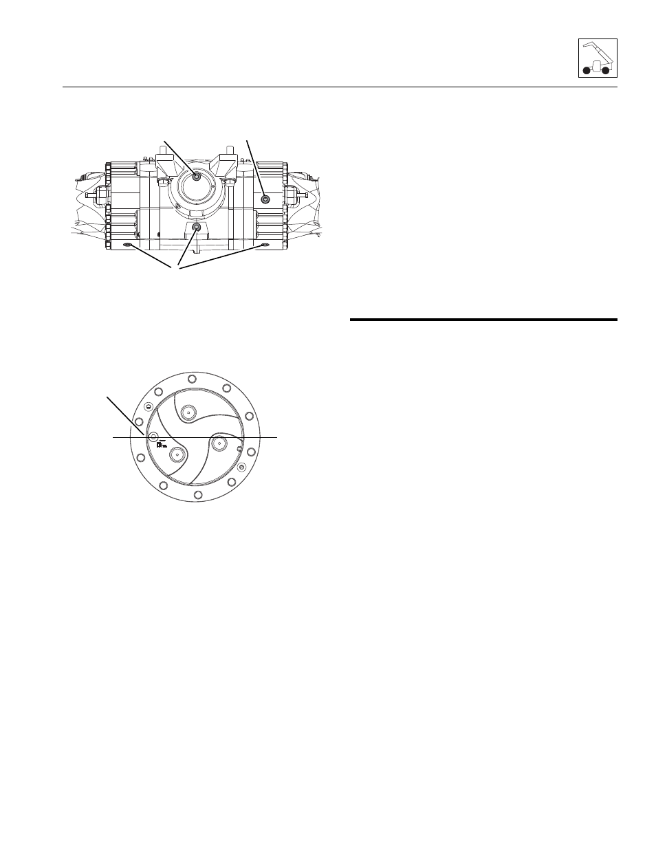
14. Tighten axle oil drain plugs (1), loosen and remove the
axle oil fill plug (3). Loosen and remove check fill plug
(4). Fill until oil level reaches bottom of check fill plug.
Refer to Section 2.5, “Fluids, Lubricants and Capacities,”
for proper oil and capacities.
15. Rotate wheel hubs 90 degrees so wheel hub drain plug
becomes the fill plug (2). Refer to Section 2.5, “Fluids,
Lubricants and Capacities,” for proper oil and capacities.
16. Install the wheel and tire assemblies. Refer to Section
5.10.2, “Installing Wheel and Tire Assembly onto
Machine.”
17. Carefully remove jack, hoist or overhead crane and sling
supporting axle.
18. Carefully raise machine using a suitable jack or hoist.
Remove supports from beneath frame and lower
machine to ground.
19. Remove blocks from front and rear of both tires on
other axle.
Note: ALWAYS use new o-rings when servicing machine.
20. Install new o-rings into fittings. Lubricate o-rings with
clean hydraulic oil.
21. Uncap and connect steering and brake lines at their axle
fittings.
22. Check hydraulic reservoir oil level.
23. Start engine. Turn steering wheel several times
lock to lock, operate frame tilt function several
times in both directions and check function of brakes.
Check for hydraulic leaks, and tighten or repair as
necessary.
24. Install fender assembly. Torque as required.
25. Properly connect battery.
26. Close and secure engine cover.
27. Remove Do Not Operate Tag from ignition key switch
and steering wheel.
Note: Service brake circuit will need to bled after axle
installation. Refer to Section 8.9.3, “Service Brake Bleeding.”
5.5
BRAKE INSPECTION
Detailed axle service instructions are provided in the Axle
Service Manual, refer to Section 5.3, “Axle Specifications and
Maintenance Information.”
M 7620
Z
3
4
1
MT0220
2