4 service brake test, 5 steering orbitrol valve, 6 outrigger/stabilizer valve and brake damper – JLG 4017RS Service Manual User Manual
Page 144: Service brake test, Steering orbitrol valve, Outrigger/stabilizer valve and brake damper
Hydraulic System
8-14
3614RS, 4017RS
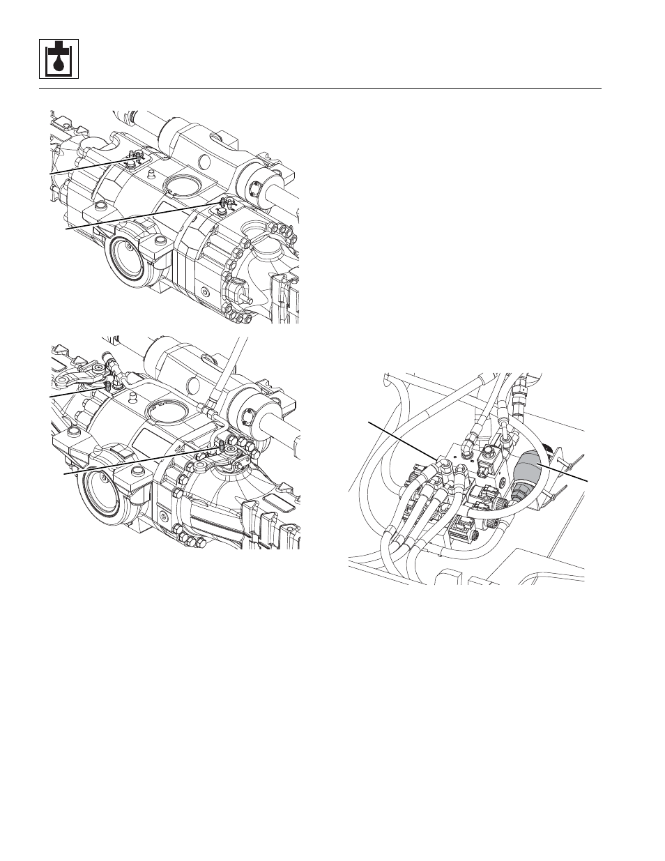
2. Remove the plastic cap from the left brake bleeder (2).
Attach one end of a length of transparent tubing over
the brake bleeder. Place the other end of this tubing in a
suitable transparent container that is partially filled with
hydraulic oil. The end of the tubing must be below the
oil level in the container.
3. DO NOT open the brake bleeder without holding the
tubing firmly on the bleeder. There is pressure at the
brakes. Carefully open the bleeder. Have the assistant
depress the brake pedal. Close the brake bleeder when
air bubbles no longer appear in the oil. Release the
brake pedal. Remove the tubing from the brake bleeder.
4. Repeat steps 2 and 3 for the right brake bleeder and the
left and right rear axle bleeders.
8.9.4
Service Brake Test
1. Install a digital or a 70 bar (1000 psi) gauge to the test
port on the brake valve (behind the front cover of the
cab).
2. Start the machine and apply pressure to the service
brake pedal. A maximum pressure of 44 bar
(638 psi) should be achieved.
3. If further testing is required, refer to Section 8.5.1,
8.9.5
Steering Orbitrol Valve
The steering orbitrol valve is located at the base of the
steering wheel shaft, concealed by the front access covers.
The valve is not serviceable and must be replaced in its
entirety if defective. For detailed information refer to Section
4.3.2, “Steering Column/Orbitrol Valve.”
8.9.6
Outrigger/Stabilizer Valve and Brake
Damper
The outrigger/stabilizer valve (3) controls the direction of
hydraulic fluid flow to each outrigger cylinder and the
stabilizer cylinder. The outrigger/stabilizer valve and brake
damper is attached inside the frame in front of the front axle.
Verify the correct operation of the outrigger/stabilizer valve
solenoids before considering replacement of the valve. Refer
to Section 9.5, “Electrical System Schematics.” The body of
the outrigger/stabilizer valve is not serviceable and must be
replaced if defective.
MZ8070
2
2
2
2
3614RS
4017RS
MZ8090
4
3