2 installing wheel and tire assembly onto machine, 7 steering angle adjustment, 8 brakes – JLG G5-18A Service Manual User Manual
Page 71: 1 brake disc inspection, Steering angle adjustment, Brakes, Installing wheel and tire assembly onto machine, Brake disc inspection
5-11
G5-18A, 2505H, 25.5
Axles, Drive Shafts, Wheels and Tires
5.6.2
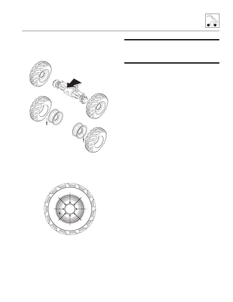
Installing Wheel and Tire Assembly
onto Machine
Note: The wheel and tire assemblies must be installed
with the directional tread pattern “arrows” facing in the
direction of forward travel.
1. Position wheel onto studs on wheel end of axle.
2. Install washers on the wheel studs.
3. Start all lug nuts by hand to prevent cross threading.
DO NOT use a lubricant on threads or nuts.
4. Tighten lug nuts in an alternating pattern as
indicated in figure. Torque to 221 lb-ft (300 Nm).
5. Remove machine from supports.
6. Remove the Do Not Operate Tags from both the
ignition key and the steering wheel.
5.7
STEERING ANGLE ADJUSTMENT
Detailed axle service instructions are provided in the Axle
Disassembly & Assembly Manual (P/N 31200451).
5.8
BRAKES
5.8.1
Brake Disc Inspection
Detailed axle service instructions are provided in the
Front Axle Disassembly & Assembly Manual
(P/N 31200419).
MAH0460
TREAD “ARROWS” MUST
POINT FORWARD
INSTALL TIRES ONTO
WHEELS TO ROTATE IN
PROPER DIRECTION
OAH0990
1
2
3
4
5
6
7
8