3 second boom section removal, Second boom section removal – JLG G5-18A Service Manual User Manual
Page 37
3-5
G5-18A, 2505H, 25.5
Boom
10. Uncap and reconnect extend/retract cylinder fittings
and plugs to extend/retract cylinder tubes and
tighten until wrench-tight. Mark fitting, then torque to
specification. Refer to Section 2.2.3, “Hydraulic
Hose Torque Chart.”
11. Uncap and reconnect tilt hoses and (if equipped)
auxiliary hoses. Attach both sets to their appropriate
fittings until wrench-tight. Mark fitting, then torque to
specification. Refer to Section 2.2.3, “Hydraulic
Hose Torque Chart.”
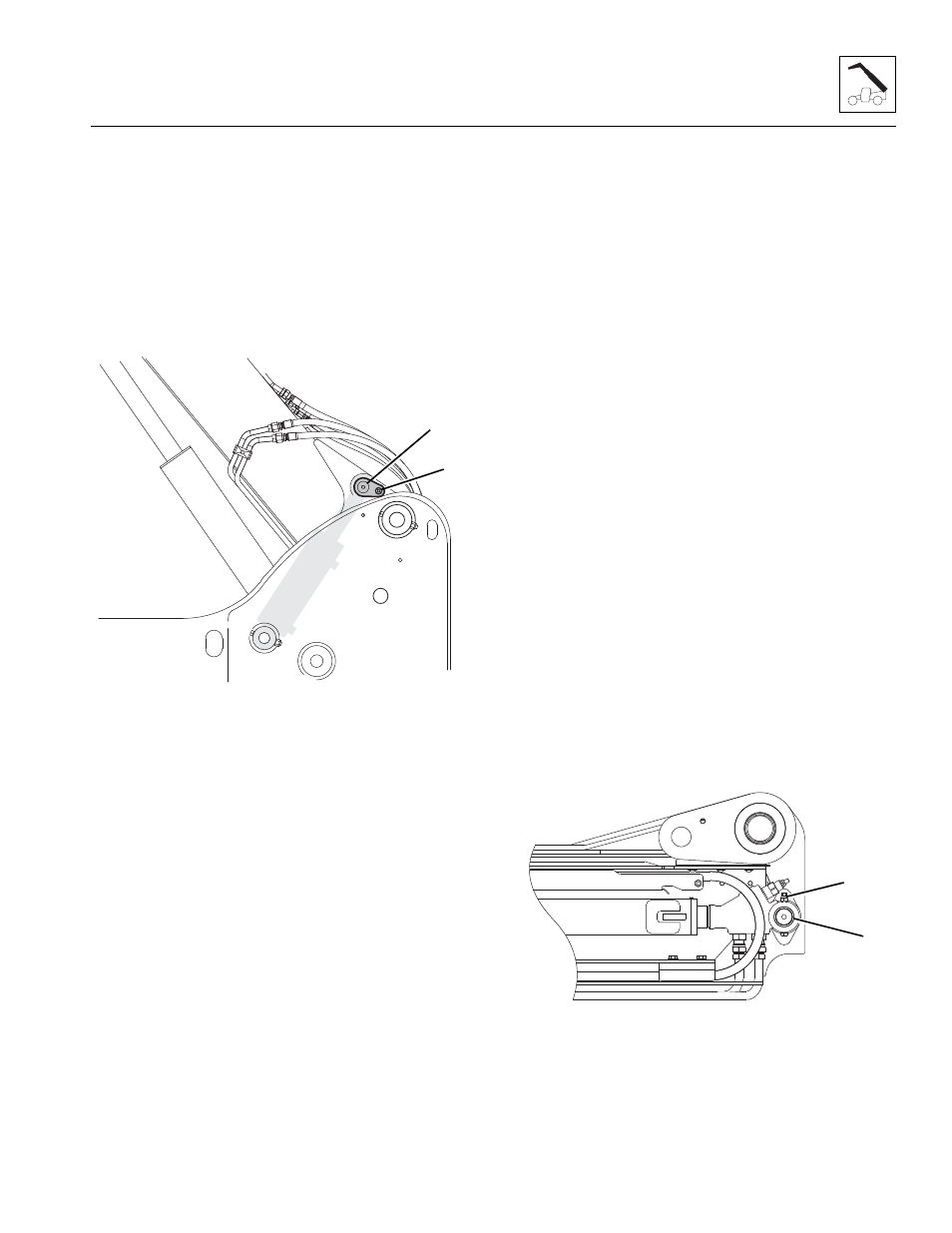
12. Raise boom to height that allows for installation of
compensating cylinder, pin (8) and lock bolt (9).
Apply locking compound and torque to
66 lb-ft (90 Nm).
13. Adjust and shim each wear pad as needed.
14. Start engine and operate all boom functions several
times to bleed any air out of hydraulic system.
15. Check for fluid leaks.
16. Check the hydraulic fluid level in tank and add fluid
as required.
17. Clean up all debris, hydraulic fluid, etc., in, on, near
and around the machine.
18. Close and secure engine cover.
19. Remove Do Not Operate Tags from both ignition key
switch and the steering wheel.
20. Install previously removed attachment to quick
attach assembly.
3.4.3
Second Boom Section Removal
1. Remove any attachment from quick attach assembly.
2. Be sure there is enough room in front of machine to
allow boom sections to be removed.
3. Park machine on a hard, level surface.
4. Fully retract boom, lower boom, place transmission
control lever in (N) NEUTRAL.
5. Engage park brake and shut engine OFF.
6. Place a Do Not Operate Tag on both ignition key
switch and steering wheel.
7. Properly disconnect battery.
8. Open engine cover. Allow system fluids to cool.
9. Remove quick attach assembly. Refer to Section
3.6.1, “Quick Attach Assembly Removal.”
10. Label and disconnect tilt hoses and (if equipped)
auxiliary hydraulic hoses attached to machine at
boom head. Plug and cap hose ends to prevent dirt
and debris from entering hydraulic system.
Note: Tag or identify each hose to corresponding fitting
it was removed from.
11. Label and disconnect extend/retract hydraulic tubes
on extend/retract cylinder at the rear of boom. Plug
and cap hose ends to prevent dirt and debris from
entering hydraulic system.
12. Remove top and side wear pads from rear of second
boom section.
Note: Tag each pad, backing plate, shim and bolts from
each location.
13. Remove lock bolt and nut (10) from rear of
extend/retract cylinder.
14. Remove extend/retract cylinder mounting pin (11).
15. Support front of boom by placing a sling behind
boom head.
MY8570
9
8
MY1960
11
10