4 lsi system calibration, Lsi system calibration – JLG G5-18A Service Manual User Manual
Page 149
9-29
G5-18A, 2505H, 25.5
Electrical System
9.11.4
LSI System Calibration
a. Standard Calibration
To calibrate the LSI, certain conditions must be met:
• The sensors must be installed according to Section
9.11.1, “LSI Axle Sensor,” and Section 9.11.2, “LSI
Boom Sensors.”
• The machine control system must be powered on for
at least 10 minutes before calibration.
• The operator must remain in the cab.
• The calibration shall be conducted with the standard
carriage and forks attached and weights as
necessary (a range of 60 - 80% of maximum weight
capacity).
• The machine must be on a level surface with the
wheels steered straight and park brake off, with
straight driving over a distance of at least 2 m (6.5 ft)
being the last movement before entering a
calibration point.
• While utilizing the LSI override button, 10 times lift
and lower the boom stopping suddenly to induce the
rear axle to bounce.
• Position the rear tires centrally on the scales.
• The calibration must be completed within 30 minutes
after starting procedure.
Calibration Procedure:
1. Start and position the machine to perform the
calibration procedure.
2. Remove the standard carriage and weight assembly.
3. Fully retract the boom and if equipped, lower the
outriggers. Shut the machine OFF.
4. With ignition key in OFF position, press and hold
SYSTEM CHECK button on LSI display and turn
ignition key to engine START position. Release the
ignition key when engine start is achieved, but
continue to hold SYSTEM CHECK button on LSI
display until the orange LED on LSI display goes out
and buzzer sounds (approximately 3 seconds).
Release SYSTEM CHECK button.
5. The LEDs will perform a rolling sequence. When
only the third green LED illuminates, press the
SYSTEM CHECK button.
6. The first green LED then illuminates. With no
attachment, outriggers down (if equipped) and boom
fully retracted, lift boom to maximum boom angle.
7. Press the SYSTEM CHECK button on the LSI
display and release. The first 3 green LEDs will
illuminate. The third then second green LEDs will go
out as the calibration point is recorded.
8. The first green LED goes out and buzzer sounds
then the red LED illuminates.
9. Lower boom until level. Pressing the LSI Override
button may be required to lower the boom.
10. Attach the previously removed standard carriage,
forks and weight.
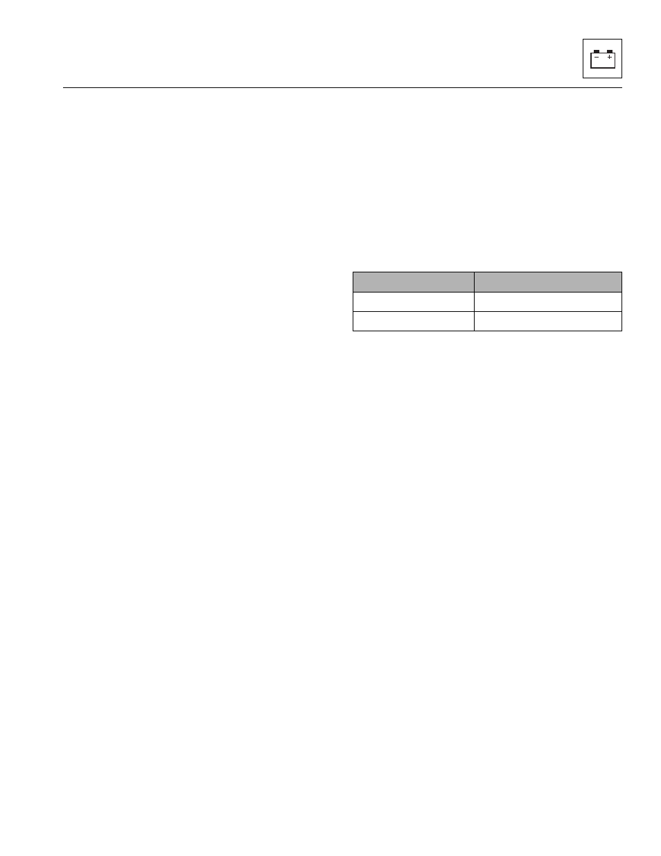
11. Slowly extend the boom until the rear axle weight in
the following table is achieved.
12. Press the SYSTEM CHECK button on the LSI
display and release. As the calibration point is
recorded, buzzer sounds and the LEDs will flash and
perform a sequence until all are flashing.
13. Perform the LSI- CAN Check PT to finalize the
calibration. Refer to Section 9.11.5, “LSI-CAN Check
PT.”
Model
Weight on Rear Axle
2505H & 25.5 CE
700 ± 20 lb (318 9 kg)
2505H & 25.5 AUS
1102 ± 29 lb (500 ± 9 kg)