JLG G5-18A Service Manual User Manual
Page 150
Electrical System
9-30
G5-18A, 2505H, 25.5
b. Field Calibration
To calibrate the LSI, certain conditions must be met:
• The sensor must be installed according to Section
9.11.1, “LSI Axle Sensor,” and Section 9.11.2, “LSI
Boom Sensors.”
• The test weight matches the model being calibrated
in the table shown on page 9-30.
• The calibration shall be conducted with standard
carriage and forks attached to the machine.
• While utilizing the LSI override button, 10 times lift
and lower the boom stopping suddenly to induce the
rear axle to bounce.
Note: If the test weight is not known, follow steps 1 & 2.
1. With the estimated test weight on the forks, start the
machine and extend the boom horizontally until the
machine starts to tip. This point should be at an
extension of Xtip (1) of the second boom section. If
the machine is not tipping at this extension, weight
needs to be added or removed from the forks.
2. By confirming that the machine tips at this point, the
correct amount of weight is now on the forks.
3. The machine control system must be powered on for
at least 10 minutes before calibration.
4. The machine must be on a level surface with the
wheels steered straight and park brake OFF. Drive
the machine forward over a distance of at least 2 m
(6.5 ft) before entering a calibration point.
5. Place test weight on ground, apply park brake and
shut engine OFF. Do Not move machine.
Field Calibration Procedure:
Note: The following procedure must be completed
within 30 minutes of starting the procedure.
1. With ignition key in OFF position, press and hold
SYSTEM CHECK button on LSI display and turn
ignition key to engine START position. Release the
ignition key when engine start is achieved, but
continue to hold SYSTEM CHECK button on LSI
display until the orange LED on LSI display goes out
and buzzer sounds (approximately 3 seconds).
Release SYSTEM CHECK button.
2. The LEDs will perform a sequence. When only the
third green LED illuminates, press the SYSTEM
CHECK button.
3. The first green LED then illuminates. With no
attachment and boom retracted, lift boom fully.
4. Press the SYSTEM CHECK button on the LSI
display and release. The first 3 green LEDs will
illuminate. The third then second green LEDs will go
out as the calibration point is recorded.
5. The first green LED goes out and buzzer sounds
then the red LED illuminates.
6. Lower boom and without moving the machine, pick
up the proper test weight (W) listed in the table.
Pressing the LSI Override button may be required to
lower the boom.
7. With the boom horizontal, slowly extend the boom to
the distance of Xcal (2). The proper calibration
weight is now on the rear axle and the LSI can now
be calibrated.
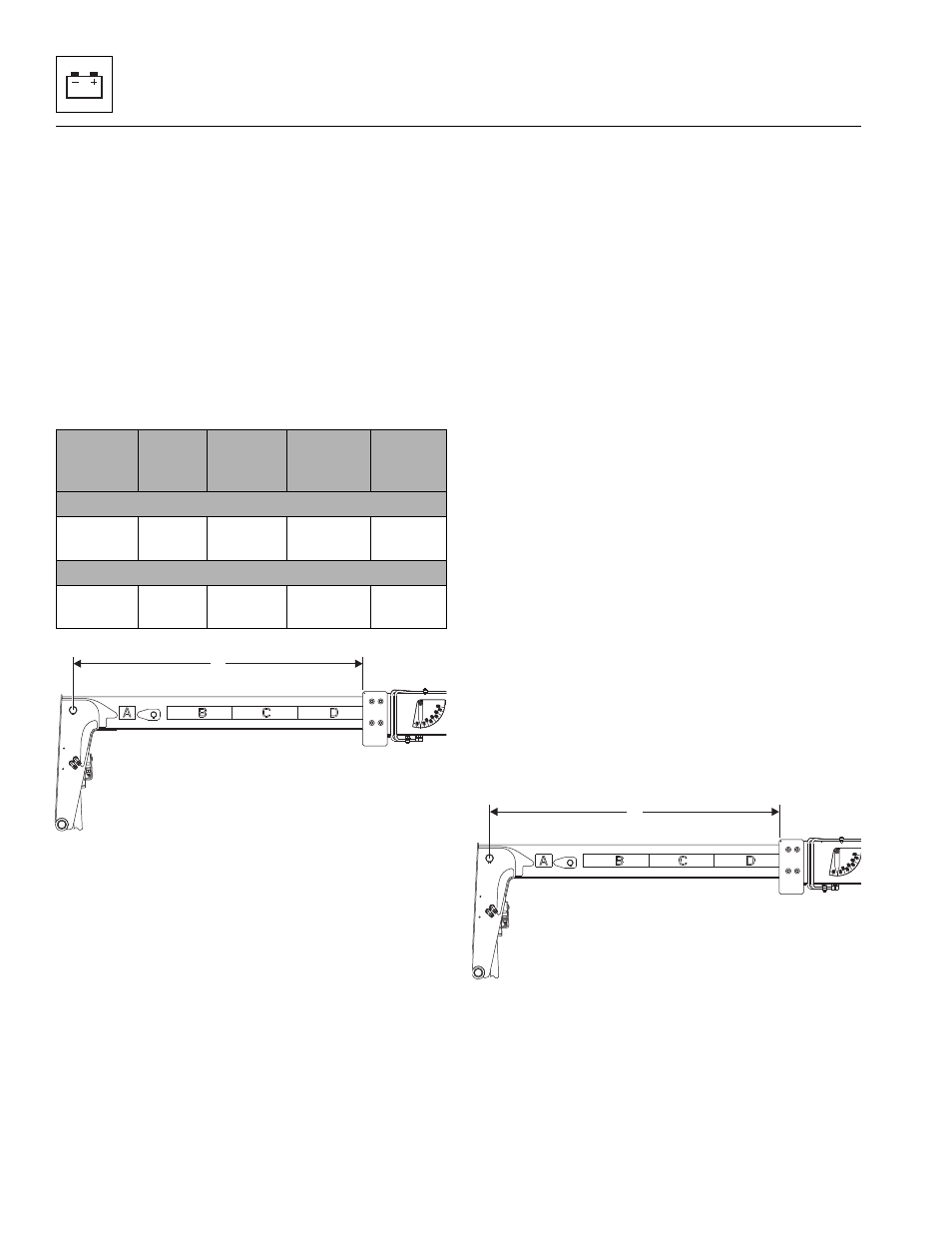
Model
Market
Test
Weight
(W)
Xtip (1)
Xcal (2)
With Manual Quick Attach
2505H
& 25.5
CE &
AUS
2000 kg
(4408 lb)
1225 mm
(48.25 in)
978 mm
(38.5 in)
With Hydraulic Quick Attach
2505H
& 25.5
CE &
AUS
2000 kg
(4408 lb)
1200 mm
(47.25 in)
952 mm
(37.5 in)
MU7740
1
MU7740
2