3 brake pedal and valve, Brake pedal and valve – JLG G5-18A Service Manual User Manual
Page 53
4-5
G5-18A, 2505H, 25.5
Cab
4.4.3
Brake Pedal and Valve
a. Brake Valve Removal
Refer to Section 8.11.2, a. “Service Brake Valve
Removal,” for removal information.
b. Brake Valve Installation
Refer to Section 8.11.2, b. “Service Brake Valve
Installation,” for installation information.
c. Service Brake Pedal Removal
1. Park machine on a hard, level surface.
2. Fully retract boom, lower boom, place transmission
control lever in (N) NEUTRAL.
3. Engage park brake and shut engine OFF.
4. Place a Do Not Operate Tag on both ignition key
switch and steering wheel.
5. Properly disconnect battery.
6. Open engine cover. Allow system fluids to cool.
7. Remove the lower dash cover.
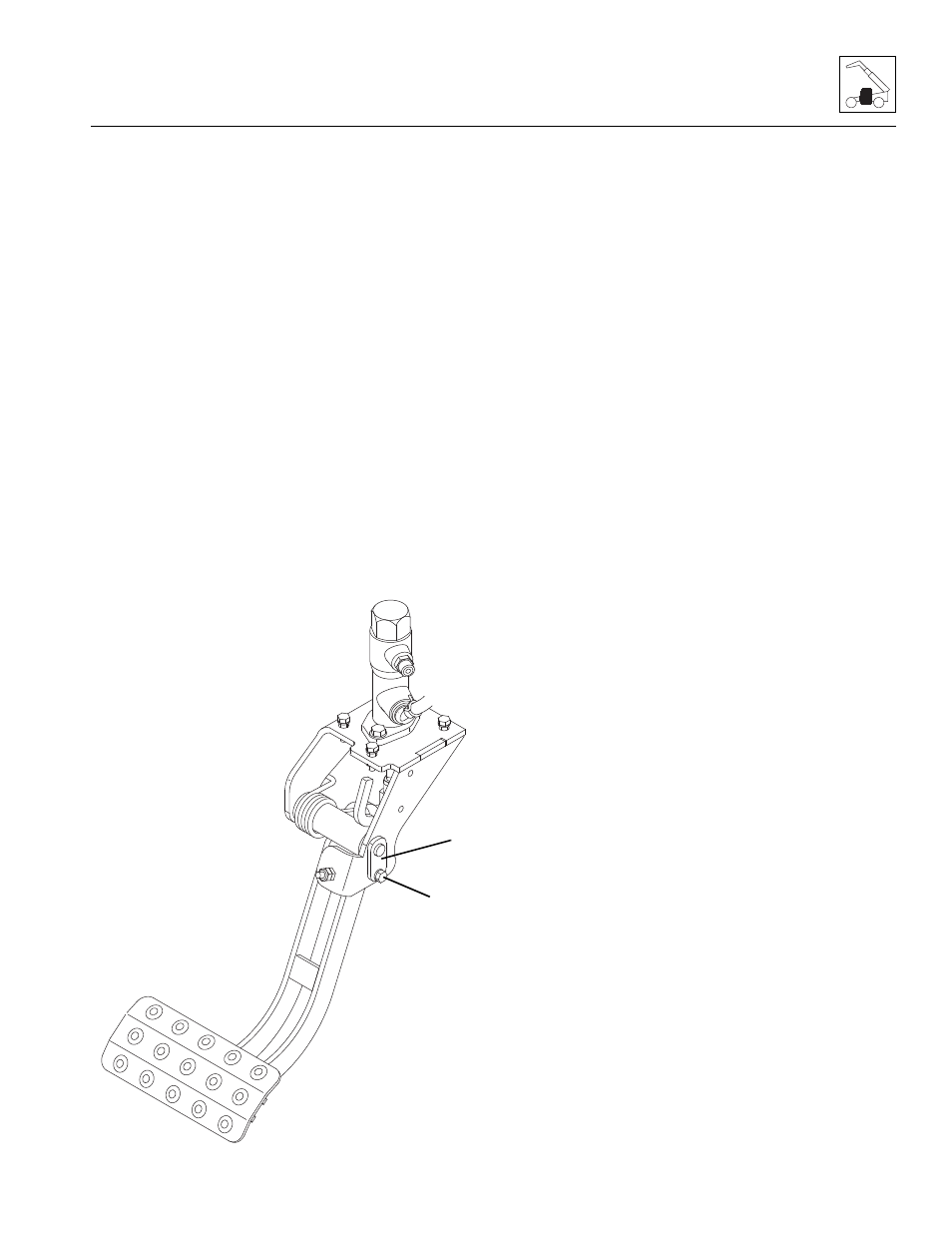
8. Remove hardware (10).
9. Remove pin (11) and return spring securing service
brake pedal to cab.
10. Remove service brake pedal from cab.
d. Service Brake Pedal Installation
1. Position service brake pedal in its mounting location
within cab.
2. Install brake pedal being careful to reposition brake
plunger yoke.
3. Install return spring and pin (11).
4. Install hardware (10) securing pin.
5. Adjust brake pedal as needed.
6. Install and secure lower dash cover.
7. Properly connect battery.
8. Close and secure engine cover.
9. Remove a Do Not Operate Tag on both ignition key
switch and steering wheel.
MY8860
11
10