11 variable speed fan valve, Variable speed fan valve – JLG G5-18A Service Manual User Manual
Page 114
Hydraulic System
8-24
G5-18A, 2505H, 25.5
6. Install the solenoid valve and cartridge in the quick
attach valve housing.
c. Quick Attach Installation
1. Attach the quick attach valve to the fittings on the
boom head.
2. Connect the hydraulic hoses, fittings, solenoid wire
terminal leads, etc., to the quick attach.
3. Properly connect the battery.
4. Start the engine and run at approximately 1/3-1/2
throttle for about one minute, without moving the
machine or operating any hydraulic functions.
5. Inspect for leaks and check the level of the hydraulic
fluid in the reservoir. Shut the engine OFF.
Note: Check for leaks and repair as required before
continuing. Add hydraulic fluid to the reservoir as needed.
6. Wipe up any hydraulic fluid spillage in, on, near and
around the machine, work area and tools.
7. Close and secure the battery and engine covers.
8. Remove the Do Not Operate Tags from both the
ignition key and the steering wheel.
d. Quick Attach Valve Test
1. Turn the ignition switch to the ON position, activate
the quick attach switch to switch the auxiliary
position or the quick attach position.
2. If further troubleshooting is required, refer to Section
8.7, “Hydraulic Schematic,” or Section 9.4, “Electrical
System Schematics.”
8.11.11
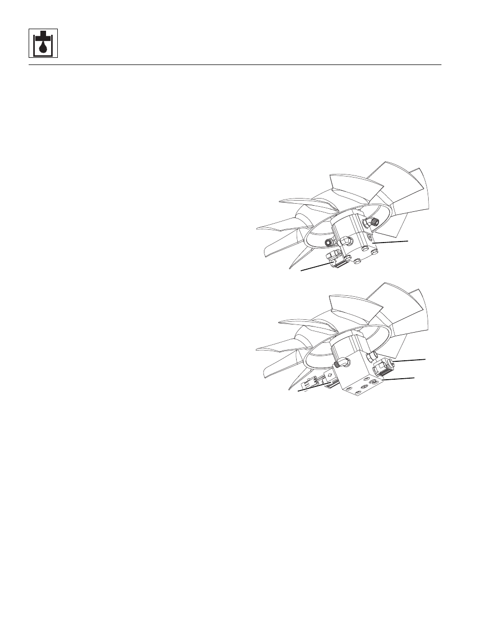
Variable Speed Fan Valve
The variable speed fan valve is located on the bottom
side of the Radiator assembly.
Place a piece of paper over the face of the radiator core.
If the paper is held in place, the fan is rotating in the right
direction.
The housing of the variable fan valve is not serviceable
and must be replaced if defective.
a. Variable Speed Fan Valve Removal
1. Park the machine on a firm, level surface, fully
retract the boom, raise the boom, place the
transmission control lever in (N) NEUTRAL, engage
the park brake and shut the engine OFF.
2. Properly support the boom.
3. Place a Do Not Operate Tag on both the ignition key
switch and the steering wheel, stating that the
machine should not be operated.
4. Open the battery and engine covers. Allow the
system fluids to cool.
5. Properly disconnect the battery.
6. Refer to Section 7.2.2, “Radiator/Oil Cooler
Replacement,” for detailed removal instructions.
7. Label or otherwise mark the hydraulic hoses in
relation to the variable speed fan valve (1).
Disconnect and cap all hoses, fittings, solenoid wire
terminal leads, etc.
8. Remove the variable speed fan valve from the
machine. Wipe up any hydraulic fluid spillage in, on,
near and around the machine.
b. Variable Speed Fan Valve Disassembly, Cleaning,
Inspection and Assembly
1. Place the variable speed fan valve assembly on a
suitable work surface.
2. Remove the solenoid valve and cartridge (2) from
the variable speed fan valve housing.
3. Clean all components with a suitable cleaner before
inspection.
MY8680
1
2
VARIABLE SPEED FAN
(if equipped)
VARIABLE SPEED
REVERSING FAN
(if equipped)
1
2
2