4 second boom section installation, Second boom section installation – JLG G5-18A Service Manual User Manual
Page 38
Boom
3-6
G5-18A, 2505H, 25.5
16. Pull second boom section out of first boom section
approximately 6 in to 8 in (15 cm to 20 cm).
17. Pull tilt hoses and (if equipped) auxiliary hydraulic
hoses through rear of boom.
18. Remove top, side and bottom wear pads from front
of first boom section.
Note: Tag each pad, backing plate, shim and bolts from
each location.
Note: The use of two slings will allow for better stability.
19. Pull second boom section halfway out of first boom
section, reposition sling(s), balancing second boom
section and remove from first boom section.
20. Place second boom section on suitable stands to
begin tear down.
21. Inspect boom and welds. Consult local JLG Dealer if
structural damage is detected.
22. Inspect hoses, hardware, wear pads, mounting
points and other components visible with first boom
section. Replace any item if damaged.
23. Inspect all wear pads for wear. (Refer to Section
3.5.1, “Wear Pad Inspection.”)
3.4.4
Second Boom Section Installation
Note: Lubrication of boom wear surfaces with grease is
recommended to keep boom wear surfaces lubricated
properly. Lubrication of boom wear surfaces is also
recommended when machine is stored, to help
prevent rusting. Refer to Section 2.4, “Fluids, Lubricants
and Capacities.”
1. If previously removed, install extend/retract cylinder
into rear of second boom section. Pin and clip barrel
end of cylinder in place.
2. Install wear pads, shims and bolts to their proper
location at front inside of first boom section.
DO NOT tighten wear pads at this time.
3. Feed the tilt cylinder hoses and if equipped, the
auxiliary hoses through the channel above the
extend/retract cylinder.
4. Using suitable sling(s), balance second boom
section, lift and carefully guide boom into place.
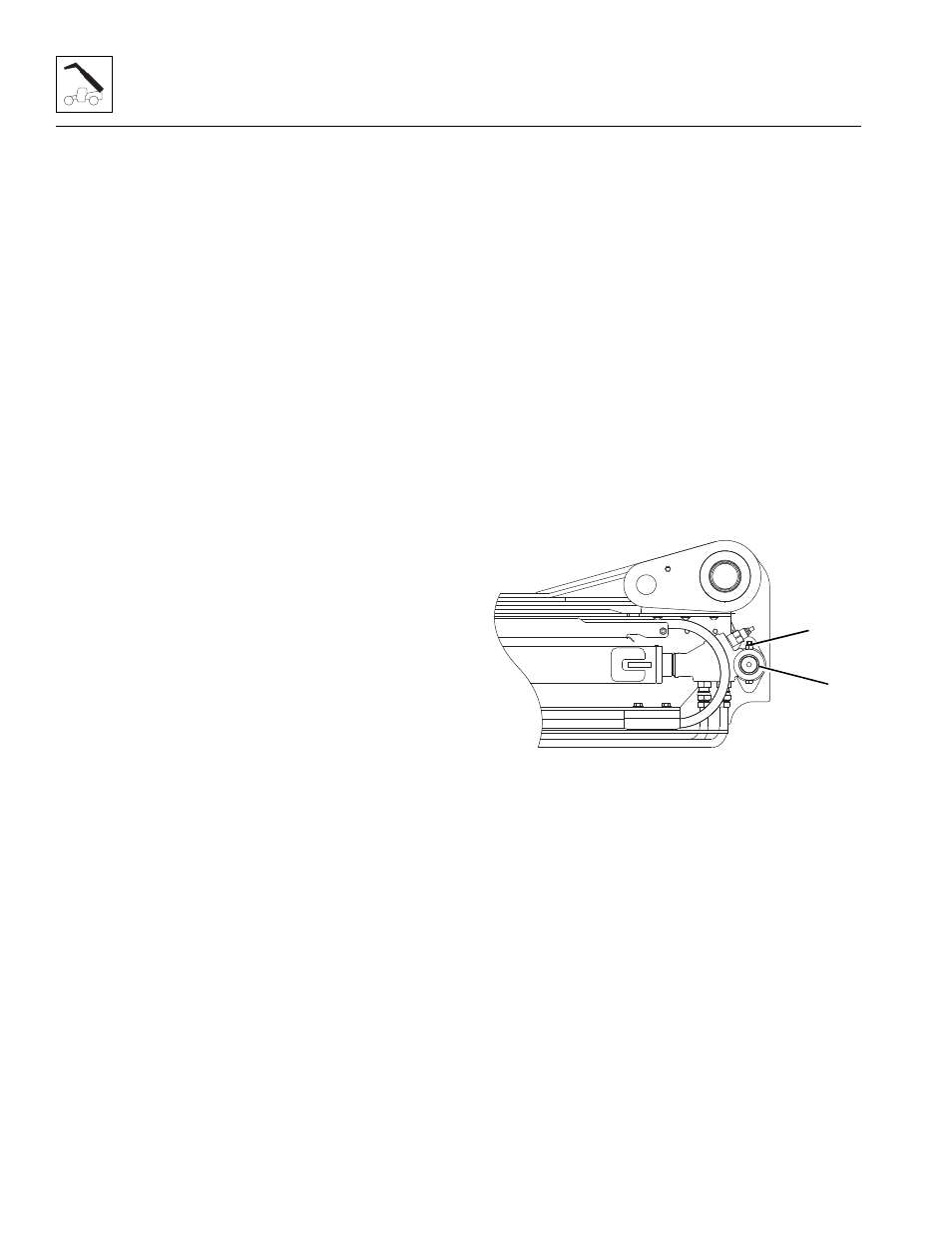
5. Install extend/retract cylinder mounting pin (11).
6. Install lock bolt and nut (10) at rear of
extend/retract cylinder.
7. Install wear pads, shims and bolts previously
removed from rear of second boom section.
DO NOT tighten the wear pads at this time.
8. Uncap and reconnect extend/retract cylinder fittings
and plugs from extend/retract cylinder tubes and
tighten until wrench-tight. Mark fitting, then torque to
specification. Refer to Section 2.2.3, “Hydraulic
Hose Torque Chart.”
9. Uncap and reconnect tilt hoses and (if equipped)
auxiliary hoses. Attach both sets to their appropriate
fittings until wrench-tight. Mark fitting, then torque to
specification. Refer to Section 2.2.3, “Hydraulic
Hose Torque Chart.”
10. Adjust and shim each wear pad as needed.
11. Properly connect battery.
MY1960
11
10