4 hand brake valve (2505h & 25.5), Hand brake valve (2505h & 25.5) – JLG G5-18A Service Manual User Manual
Page 107
8-17
G5-18A, 2505H, 25.5
Hydraulic System
4. Properly connect the battery.
5. Start the engine and run at approximately one-third
to one-half throttle for about one minute, without
moving the machine or operating any hydraulic
functions.
6. Inspect the park brake valve and connections for
leaks, and check the level of the hydraulic fluid in the
reservoir. Shut the engine OFF.
7. Install the park brake/cover with the four capscrews.
8. Wipe up any hydraulic fluid spillage in, on, near and
around the machine, work area and tools.
9. Close and secure the battery and engine covers.
10. Remove the Do Not Operate Tags from both the
ignition key and the steering wheel.
d. Park Brake Valve Test.
1. Start the machine and engage the shift lever to the
forward position. Slowly depress the throttle to mid
idle. The parking brake will not allow the machine to
move.
2. If further troubleshooting is required, refer to the
Section 8.7, “Hydraulic Schematic,” or Section 9.4,
“Electrical System Schematics.”
8.11.4
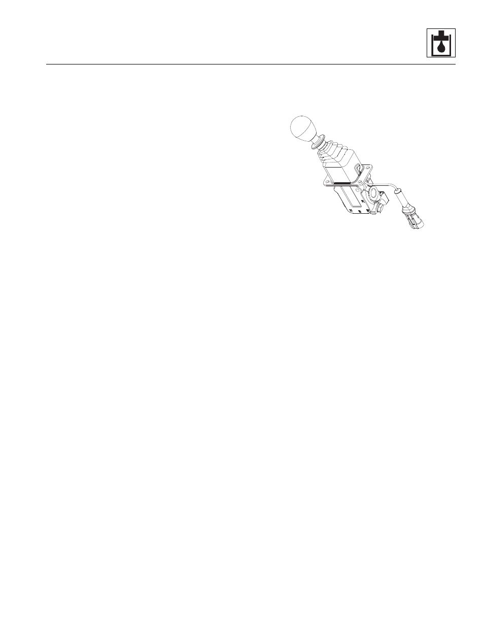
Hand Brake Valve (2505H & 25.5)
The hand brake valve is located in the cab, beside the
seat.
a. Hand Brake Valve Removal
1. Park the machine on a firm, level surface, fully
retract the boom, lower the boom, place the
transmission control lever in (N) NEUTRAL, engage
the hand brake and shut the engine OFF.
2. Place a Do Not Operate Tag on both the ignition key
switch and the steering wheel, stating that the
machine should not be operated.
3. Open the battery and engine covers. Allow the
system fluids to cool.
4. Properly disconnect the battery.
5. Remove the two capscrews holding the cover below
the seat. The hand brake valve is mounted on the
mounting plate attached to the seat base.
6. Label, disconnect and cap the hydraulic hoses on
each side and bottom of the hand brake valve.
Disconnect and cap all hoses, fittings, etc.
7. Remove the four capscrews and lockwashers
mounting the hand brake valve to the mounting
plate.
b. Hand Brake Valve Disassembly, Cleaning,
Inspection and Assembly
1. Place the hand brake valve on a suitable work
surface.
2. Clean all components with a suitable cleaner before
inspection.
3. Inspect internal passageways of the hand brake
manifold and valve for wear, damage, etc. If inner
surfaces of the manifold DO NOT display an ultra-
smooth, polished finish, or components are
damaged in any way, replace the manifold or
appropriate part. Often, dirty hydraulic fluid causes
failure of internal seals and damage to the polished
surfaces within the unit.
Note: ALWAYS replace seals, o-rings, gaskets, etc.,
with new parts to help ensure proper sealing and
operation. Lubricate seals and o-rings with clean
hydraulic oil.
c. Hand Brake Valve Installation
1. Install the Hand brake valve with the four
lockwashers and capscrews to the mounting plate.
Note: ALWAYS replace seals, o-rings, gaskets, etc.,
with new parts to help ensure proper sealing and
operation. Lubricate seals and o-rings with clean
hydraulic oil.
2. Use new oiled o-rings as required. Uncap, reattach
and secure the three hoses.
3. Check the routing of all hoses for sharp bends or
interference with any rotating members, and install
tie wraps and/or protective conduit as required.
4. Properly connect the battery.
5. Start the engine and run at approximately one-third
to one-half throttle for about one minute, without
moving the machine or operating any hydraulic
functions.
MU7710