2 lsi boom sensors, Lsi boom sensors – JLG G5-18A Service Manual User Manual
Page 147
9-27
G5-18A, 2505H, 25.5
Electrical System
a. LSI Axle Sensor Removal
1. Remove any fork carrier or attachment from the
machine.
2. Park the machine on a firm, level surface, level the
machine, fully retract the boom, fully raise the boom,
place the transmission control lever in (N)
NEUTRAL, engage the park brake and shut the
engine OFF.
3. Place a Do Not Operate Tag on both the ignition key
switch and the steering wheel, stating that the
machine should not be operated.
4. Open the battery and engine covers. Allow the
engine to cool.
5. Properly disconnect the battery.
6. Disconnect the LSI electrical connector.
7. Loosen, remove and discard the two bolts holding
the LSI assembly to the rear axle.
8. Remove and discard the sensor assembly.
b. LSI Axle Sensor Installation
1. Ensure threads of both bolt holes are clean and free
from rust, water and debris.
2. Clean the bare metal with a degreasing agent,
Loctite
®
7063™.
3. Remove any excess degreasing agent and allow to
dry.
4. Apply a thin film of Loctite
®
F246™ adhesive to the
flat metal surface of the sensor, ensuring the
adhesive is spread evenly over the entire surface.
Note: Follow all adhesive manufacturer’s
recommendations including storage life.
5. Fit the sensor, ensuring the lead exits in the corner
direction. Secure with two new bolts - Socket HD
Capscrew M10x35x1.5, Grade 12.9.
Note: It is important to prevent distortion of the sensor
element, therefore tighten each bolt finger tight.
Alternately tighten each bolt to 26 lb-ft (35 Nm) and
finally to 52-59 lb-ft (70-80 Nm).
6. Permanently mark position of bolt head and sensor
body.
7. Leave the machine undisturbed for a minimum of 6
hours before moving.
8. Plug the electrical connector into the sensor
assembly.
9. Properly connect the battery.
10. Close and secure the battery and engine covers.
11. Remove the Do Not Operate Tag from the ignition
key switch and the steering wheel.
12. Calibrate the LSI system, refer to Section 9.11.4,
9.11.2
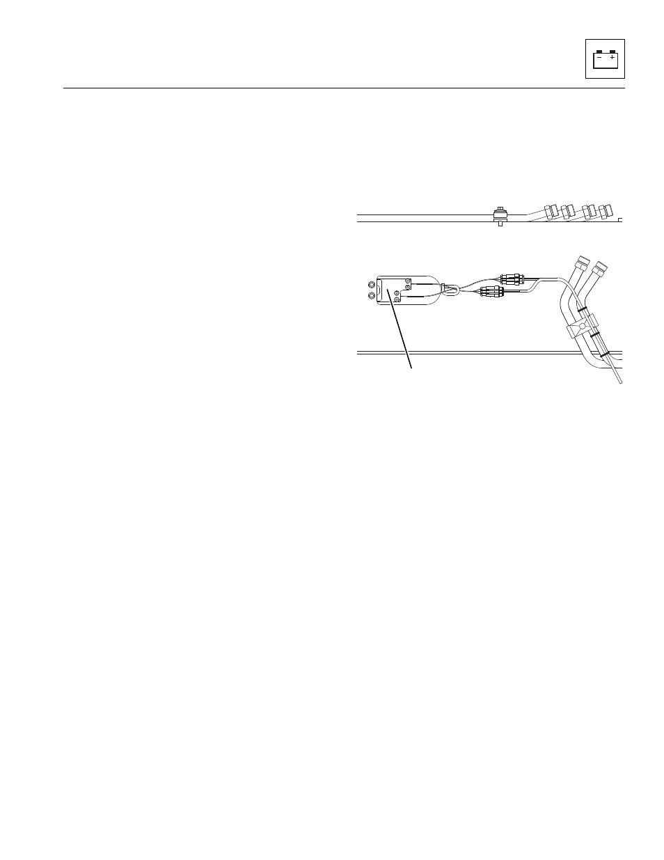
LSI Boom Sensors
The LSI sensors (2) are bolted on the left inside of the first
boom section.
a. LSI Boom Sensor Removal
1. Remove any fork carrier or attachment from the
machine.
2. Park the machine on a firm, level surface, level the
machine, fully retract the boom, fully raise the boom,
place the transmission control lever in (N)
NEUTRAL, engage the park brake and shut the
engine OFF.
3. Place a Do Not Operate Tag on both the ignition key
switch and the steering wheel, stating that the
machine should not be operated.
4. Open the battery and engine covers. Allow the
engine to cool.
5. Properly disconnect the battery.
6. Disconnect the LSI electrical connectors.
7. Loosen and remove the two bolts holding the LSI
assembly to the side of the boom.
8. Remove and discard the sensor assembly.
MAM2910
2