1 operator cab component terminology, Operator cab component terminology – JLG G5-18A Service Manual User Manual
Page 50
Cab
4-2
G5-18A, 2505H, 25.5
4.1
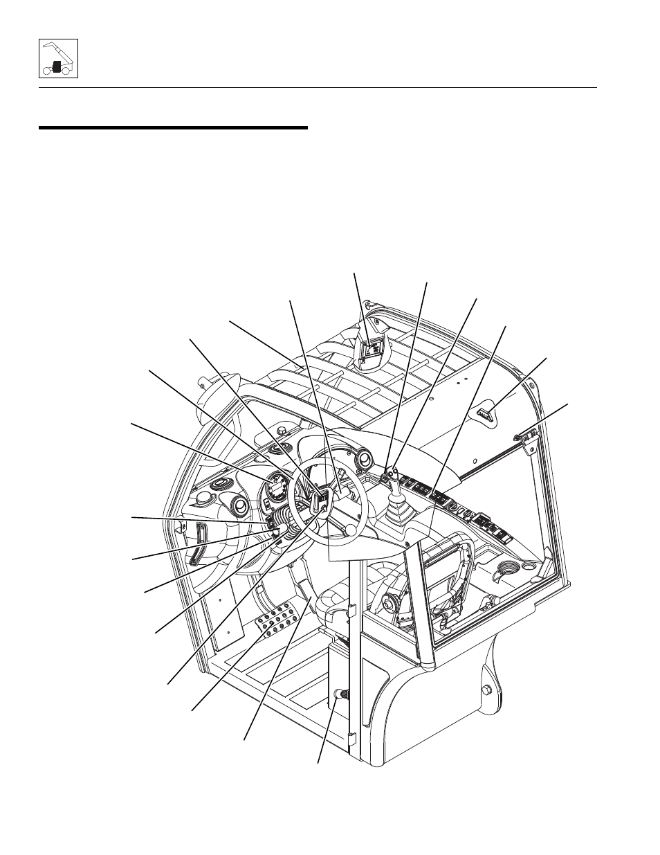
OPERATOR CAB COMPONENT
TERMINOLOGY
To understand the safety, operation and maintenance
information presented in this section, it is necessary that
the operator/mechanic be familiar with the names and
locations of the major assemblies of the machine cab and
covers. The following illustration identifies the
components that are referred to throughout this section.
MY8850
PARK BRAKE SWITCH
(G5-18A)
LSI OVERRIDE SWITCH
(2505H & 25.5)
SERVICE BRAKE PEDAL
JOYSTICK
TRANSMISSION
CONTROL LEVER
INSTRUMENT
PANEL
RIGHT HAND
CONSOLE
PARK BRAKE LEVER
(2505H & 25.5)
ACCELERATOR PEDAL
IGNITION SWITCH
TILT STEERING COLUMN
(IF EQUIPPED)
QUICK ATTACH SWITCH
(IF EQUIPPED)
STEERING WHEEL
HORN BUTTON
FRAME LEVEL
INDICATOR
LSI INDICATOR
(2505H & 25.5)
ACCESSORY CONTROL LEVER
(IF EQUIPPED)
POWER OUTLET
LONGITUDINAL LEVEL
INDICATOR (AUS)
POWER
OUTLET