7 electrical system components, 1 back-up alarm, 2 gauge cluster – JLG G5-18A Service Manual User Manual
Page 138: Electrical system components, Back-up alarm, Gauge cluster, Notice
Electrical System
9-18
G5-18A, 2505H, 25.5
9.7
ELECTRICAL SYSTEM
COMPONENTS
9.7.1
Back-up Alarm
The back-up alarm is located at the rear of the machine.
When the park brake is released and the transmission
shift control switch (transmission control lever) is shifted
to the (R) REVERSE position, the back-up alarm will
automatically sound.
CE Only -
Place the transmission control lever in (R) REVERSE to
test the back-up alarm. The back-up alarm must not
sound when the transmission control lever is in (N)
NEUTRAL or (F) FORWARD. Also, with the ignition key
switch in the RUN position, the back-up alarm will sound
when the transmission control lever is shifted into the (R)
REVERSE position.
a. Disassembly
DO NOT disassemble the back-up alarm. Replace a
defective or faulty alarm with a new part.
b. Inspection and Replacement
Inspect the wiring harness connector and alarm terminals
for continuity and shorting. Test the alarm by turning the
ignition key switch to the RUN position and shifting the
transmission control lever into the REVERSE position.
The alarm should sound.
Replace a defective or faulty alarm with a new part.
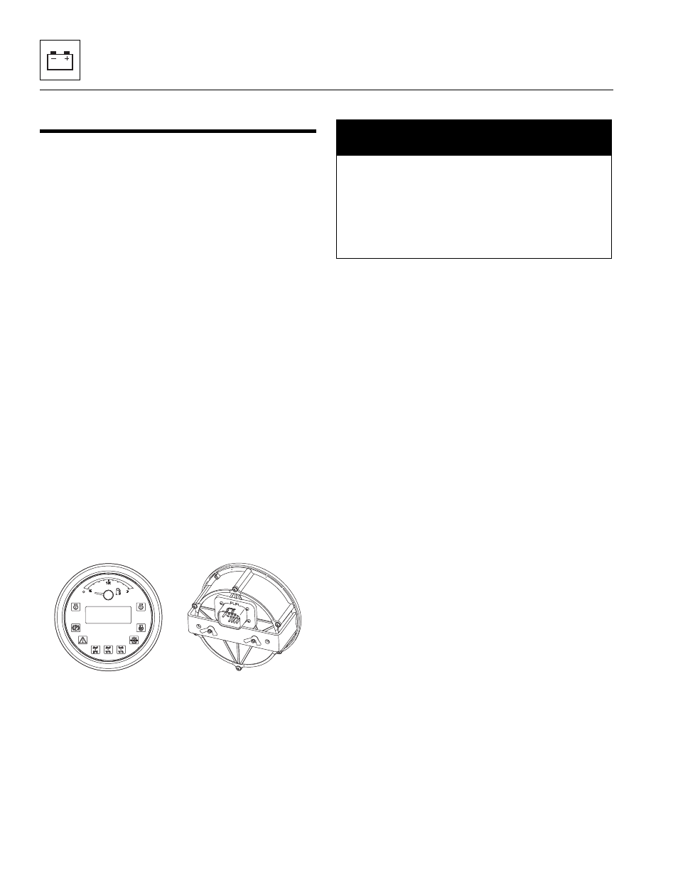
9.7.2
Gauge Cluster
a. Removal
1. Park the machine on a firm, level surface, level the
machine, fully retract the boom, lower the boom,
place the transmission control lever in (N)
NEUTRAL, engage the park brake and shut the
engine OFF.
2. Place a Do Not Operate Tag on both the ignition key
switch and the steering wheel, stating that the
machine should not be operated.
3. Open the battery and engine covers. Allow the
engine to cool.
4. Properly disconnect the battery.
5. Remove the screws holding the instrument panel to
the dash.
6. Slide the instrument panel out of the operator
console.
7. Disconnect the wiring harnesses from the rear of the
gauge.
8. Remove the two wing nuts and bracket securing the
gauge to the instrument panel.
b. Installation
1. Position the gauge in the instrument panel and
secure with the previously removed bracket and
wing nuts.
2. Connect the wiring harnesses to the rear of the
gauge.
3. Position the instrument panel in the operator
console.
4. Secure to the panel with four previously removed
screws.
5. Properly connect the battery.
6. Close and secure the battery and engine covers.
7. Remove the Do Not Operate Tags from both the
ignition key and the steering wheel.
MY8830
NOTICE
Static electricity can cause damage to the operator’s
gauge. Avoid any manner of touching (hands, tools,
etc.) the printed circuit boards and terminals.
Disconnect the battery negative (-) cable at its battery
terminal before beginning this procedure. Failure to
comply can result in damage and/or malfunction of the
gauge.