3 lsi modules, Lsi modules – JLG G5-18A Service Manual User Manual
Page 148
Electrical System
9-28
G5-18A, 2505H, 25.5
b. LSI Sensor Boom Installation
1. Mount the LSI sensor to the side of the first boom
section with the previously removed hardware. Do
Not tighten the mounting bolts at this time.
2. Shim the LSI sensor within 2-3 mm (0.08-0.11in) of
the second boom section. Tighten and torque the
mounting bolts as required.
3. Plug the electrical connector into the sensor
assembly.
4. Properly connect the battery.
5. Close and secure the battery and engine covers.
6. Remove the Do Not Operate Tags from both the
ignition key and the steering wheel.
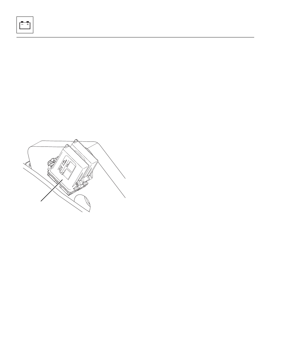
9.11.3
LSI Modules
The LSI modules (3) are bolted to the frame at the inside
left rear corner.
a. LSI Module Removal
1. Remove any fork carrier or attachment from the
machine.
2. Park the machine on a firm, level surface, level the
machine, fully retract the boom, fully raise the boom,
place the transmission control lever in (N)
NEUTRAL, engage the park brake and shut the
engine OFF.
3. Place a Do Not Operate Tag on both the ignition key
switch and the steering wheel, stating that the
machine should not be operated.
4. Open the battery and engine covers. Allow the
engine to cool.
5. Properly disconnect the battery.
6. Disconnect the LSI modules electrical connectors.
7. Loosen and remove the two bolts holding the LSI
modules to the side of the frame.
8. Remove each module.
DO NOT disassemble the module(s). The module(s) are
not serviceable. Replace module(s) if found to be
defective.
b. LSI Module Installation
1. Mount the LSI modules to the side of the frame with
the previously removed hardware. Tighten and
torque the mounting bolts as required.
2. Plug the electrical connector into the module
assemblies.
3. Properly connect the battery.
4. Close and secure the battery and engine covers.
5. Remove the Do Not Operate Tag from the ignition
key switch and the steering wheel.
MAM2920
3