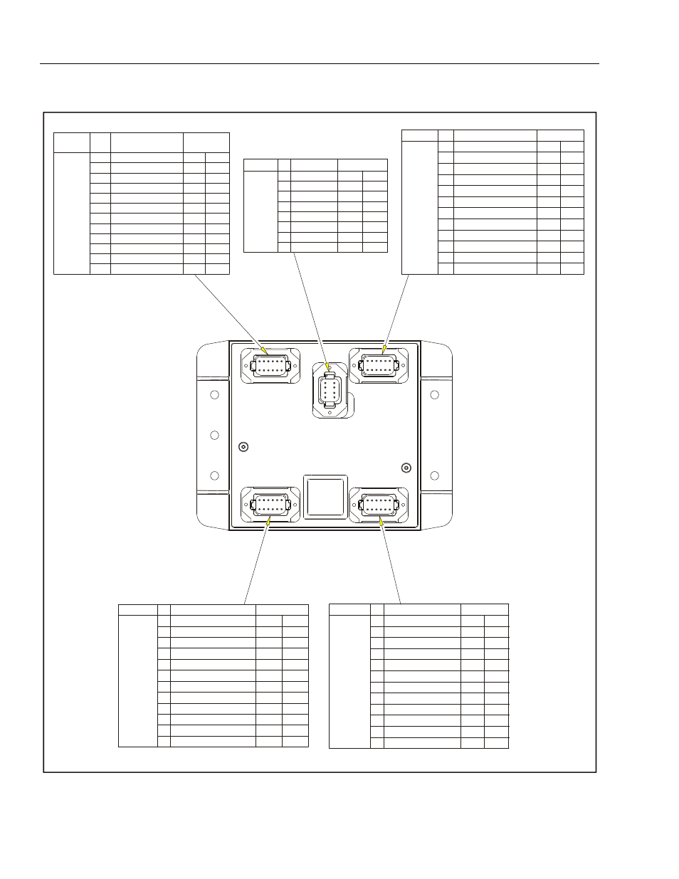
Blam control module -34, Figure 6-15. blam control module – JLG 1850SJ Service Manual User Manual
Page 316
SECTION 6 - JLG CONTROL SYSTEM
6-34
– JLG Lift –
3121619
1001112757-C
Connector
Pin
FUNCTION
Type
J1 (Grey)
1
Power Feed Thru to J2-1
Power
I/O
2
Power Feed Thru to J2-2
Power
I/O
3
Signal Feed Thru to J2-4
Digital
Input
4
Master Ground Connect
Power
Input
5
Master Ignition Connect
Power
Input
6
CANbus High
Serial
I/O
7
CANbus Low
Serial
I/O
8
CANbus Shield
Serial
I/O
9
CANbus Terminator
Serial
I/O
10
CANbus Terminator
Serial
I/O
11
Ignition
Power
Output
12
Ground
Power
Output
J4 (Grey)
1
Ignition
Power
Output
2
Ground
Power
Output
3
CANbus High
Serial
I/O
4
CANbus Low
Serial
I/O
5
CANbus Shield
Power
Input
6
Bootstrap Mode
Digital
Input
7
Ignition
Power
Output
8
Ground
Power
Output
Connector
Pin
FUNCTION
Type
J2 (Black)
1
Power Feed Thru to J1-1
Power
I/O
2
Power Feed Thru to J1-2
Power
I/O
3
Ground
Power Output
4
Spare Input
Digital
Input
5
Spare Input
Digital
Input
6
Spare Input
Digital
Input
7
Spare Input
Digital
Input
8
Main Boom Ang 1 (Gravity)
Digital
Input
9
Main Boom Ang 2 (Gravity)
Digital
Input
10
Spare Analog
Analog
Input
11
Right Drive Pump Forward
Digital Output
12
Right Drive Pump Reverse
Digital Output
Connector
Pin
FUNCTION
Type
J5 (Brown)
1
Left Drive Pump Forward
Digital Output
2
Left Drive Pump Forward
Digital Output
3
Oscillating Axles
Digital Output
4
Spare Output - D005
Digital Output
5
Spare Output - D006
Digital Output
6
Spare Output - D007
Digital Output
7
Spare Output - D008
Digital Output
8
Spare Output - D009
Digital Output
9
Ignition
Power Output
10
RS232 Receive
Serial
Input
11
RS232 Transmit
Serial
Output
12
Ground
Power Output
Connector
Pin
FUNCTION
Type
J3 (Green)
1
+5V Analog Reference
Power
Output
2
Ref Voltage from J3-1
Analog
Input
3
Ground
Power
Output
4
+5V Analog Reference
Power
Output
5
Main Cyl Angle #1(Absolute) Analog
Input
6
Ground
Power
Output
7
+5V Analog Reference
Power
Output
8
Boom Length Sensor
Analog
Input
9
Ground
Power
Output
10
+5V Analog Reference
Power
Output
11
Main Cyl Angle #2(Absolute) Analog
Input
12
Ground
Power
Output
Connector
Pin
FUNCTION
Type
Figure 6-15. BLAM Control Module