Jib lift cylinder, Jib lift cylinder -35, Cylinder barrel support -35 – JLG 1850SJ Service Manual User Manual
Page 205: Cylinder length sensor removal -35, Capscrew removal -35
SECTION 5 - BASIC HYDRAULIC INFORMATION & HYDRAULIC SCHEMATICS
3121619
– JLG Lift –
5-35
Jib Lift Cylinder
Refer to Figure 5-65.
DISASSEMBLY
CONTAMINATION MAY DAMAGE EQUIPMENT. DISASSEMBLE CYLINDER ON A
CLEAN WORK SURFACE IN A DIRT FREE WORK AREA.
1.
Connect a suitable auxiliary hydraulic power source to
cylinder port block fitting.
DO NOT FULLY EXTEND CYLINDER TO THE END OF STROKE.
RETRACT CYLINDER SLIGHTLY TO AVOID TRAPPING PRES-
SURE.
2.
Operate hydraulic power source and extend cylinder.
Shut down and disconnect power source. Adequately
support cylinder rod, if applicable.
3.
Place cylinder barrel in a suitable holding fixture.
4.
Remove cartridge-type counterbalance valve and fit-
tings from cylinder port block. Discard O-rings.
5.
If necessary, remove eight capscrews (11) and retainer
cap (10). Remove O-Ring plug (5) and setscrew (4).
Remove cylinder length sensor assembly (9) from barrel
(1).
6.
Tap around outside of cylinder head retainer with a suit-
able hammer to break thread-locking compound.
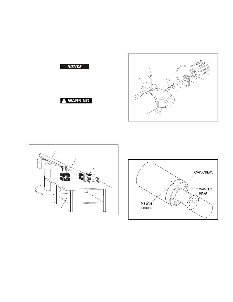
7.
Mark cylinder head and barrel with center punch marks
for later realignment. Remove eight cylinder head cap
screws.
Figure 5-62. Cylinder Barrel Support
1
6
11
9
8
7
10
4
5
Figure 5-63. Cylinder Length Sensor Removal
Figure 5-64. Capscrew Removal