12 wire rope tensioning adjustment, Boom preparation for section repositioning, Wire rope tensioning adjustment -56 – JLG 1850SJ Service Manual User Manual
Page 142: Boom preparation for section repositioning -56, Fully retracted boom section positions -56
SECTION 4 - BOOM & PLATFORM
4-56
– JLG Lift –
3121619
4.12 WIRE ROPE TENSIONING ADJUSTMENT
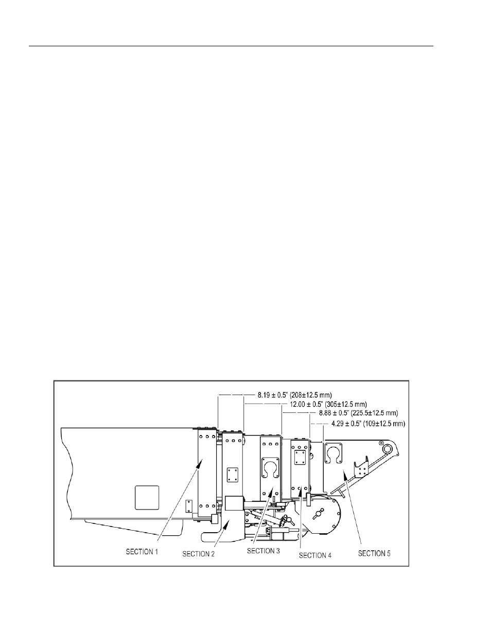
If new wire ropes are installed, there is a general starting point
for the initial exposed thread length for each wire rope
adjuster stud. Refer to Figure 4-36., Fully Retracted Boom Sec-
tion Positions for these dimensions. The proper position of the
boom sections (See Figure 4-36.) must be achieved with wire
rope equalized on both sides of the sheaves and ropes prop-
erly seated in sheave grooves prior to tensioning. This will
allow for proper tensioning of the wire ropes.
There are two major steps to this procedure:
• Positioning the boom sections so proper tensioning can be
achieved
• Tensioning the wire rope
Boom Preparation for Section Repositioning
NOTE:
Because each rope actuated section controls the move-
ment of the next smaller section, any repositioning of the
larger will affect the position of the next smaller. Correctly
position Section #3 before setting the position of Section
#4, followed by section #5.
Use the Boom Telescope function to position the boom sec-
tions. Using the wire rope adjustment nuts to position the
boom sections will cause damage to the wire rope adjust-
ers.
1.
Before making any adjustments, confirm the boom
assembly is in the fully retracted position (See Figure 4-
36., Fully Retracted Boom Section Positions).
2.
Take preliminary measurements of the position of each
boom section with the boom in the fully retracted posi-
tion and compare them to Figure 4-36., Fully Retracted
Boom Section Positions.
3.
If the measurements fall within tolerance shown on Fig-
ure 4-36., proceed to the Wire Rope Tensioning Proce-
dure.
NOTE:
Proper boom position does not confirm that rope tension is
correct, at this point.
4.
If the measurements do not fall within the tolerances in
Figure 4-36., adjust the position using the re-position
procedures in this sub-section
BOOM SECTION #2 REPOSITIONING:
NOTE:
Boom Section #2 is positioned by the telescope cylinder. No
adjustments to this section are necessary. The wire ropes
within this assembly only control the movement of the
remaining smaller sections.
Figure 4-36. Fully Retracted Boom Section Positions