Galaxy® co2 sensor setup — instructions – Eppendorf Galaxy Gas Analyzer User Manual
Page 9
9
Galaxy® CO2 Sensor Setup — Instructions
Fitting the new Parts
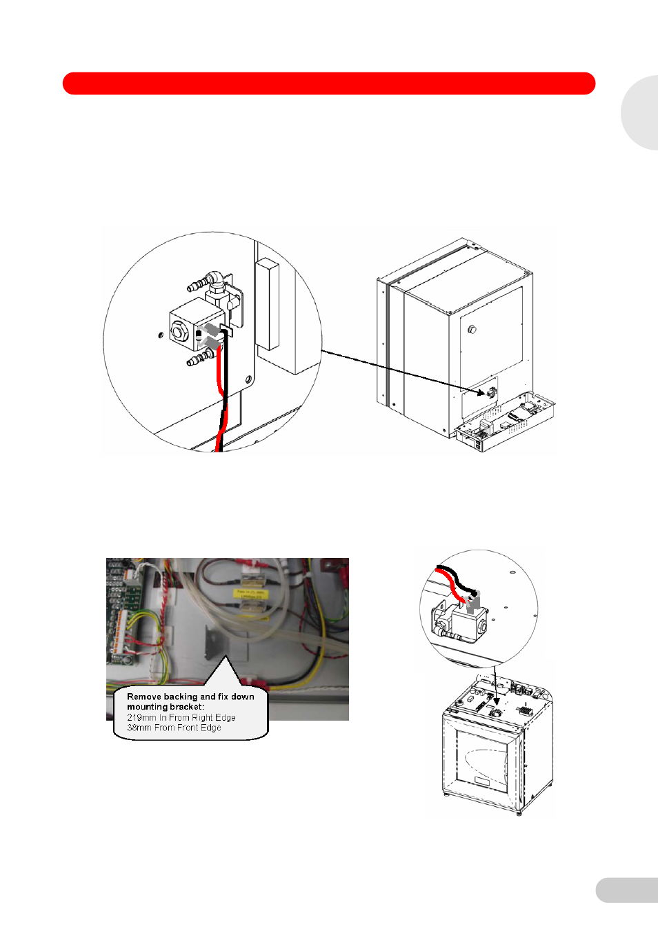
8. Solenoid Valve fitting:
170 R - Mount the Solenoid Valve to the new cover plate using the fixings supplied and fit the
new cover plate in the position shown in the image below using the 4 x Pozidriv head screws
which were kept aside earlier. Route the Red/Black wires from the Solenoid Valve along
existing cable route to the Expansion PCB, secure with zip ties. The tubing will be connected
when fitting the new CO
2
Sensor.
48 R – Fit the 48 R Solenoid Valve mounting bracket with self adhesive backing to the
equipment tray in the position shown in the image below.
Screw Valve to bracket using screws supplied and route the Red/Black wiring for the Pump
back to the expansion PCB area. The tubing will be connected when fitting the new CO
2
Sensor.
9. Cable zip tie all wires in place to secure to tray.
1
Galaxy 170 R / 48 R 120 V / 230 V CO
2
Incubators
- epMotion 96 (76 pages)
- epMotion 5070 (100 pages)
- epMotion 5075 (130 pages)
- Centrifuge 5427 R (64 pages)
- Centrifuge 5427 R (104 pages)
- White Paper 14 (8 pages)
- Rolling Cabinet (34 pages)
- Mastercycler nexus (142 pages)
- Mastercycler nexus (118 pages)
- Concentrator plus (New Design) (48 pages)
- Concentrator plus (43 pages)
- Easypet 3 (38 pages)
- Xplorer (74 pages)
- Xplorer Adjustment (26 pages)
- AF2200 Plate Reader (72 pages)
- AF2200 Plate Reader (78 pages)
- G0.5 µPlate (32 pages)
- BioSpectrometer basic (104 pages)
- BioSpectrometer kinetic (106 pages)
- BioSpectrometer fluorescence (102 pages)
- Micro Test Tubes (5 pages)
- Microplates (10 pages)
- PiezoXpert (34 pages)
- Eporator (38 pages)
- MiniSpin (25 pages)
- MiniSpin (20 pages)
- Centrifuge 5702 (32 pages)
- 5702 Centrifuge (27 pages)
- 5702 Centrifuge (32 pages)
- C5702 RH Centrifuge (32 pages)
- 5418 Centrifuge (80 pages)
- 5418 Centrifuge (48 pages)
- 5424 Centrifuge (71 pages)
- 5424 Centrifuge (44 pages)
- 5430 Centrifuge (88 pages)
- 5430 Centrifuge (130 pages)
- 5804 Centrifuge (95 pages)
- 5804 Centrifuge (127 pages)
- 5804 Centrifuge (129 pages)
- TransferMan4 r (102 pages)
- TransferMan4 m (96 pages)
- InjectMan 4 (100 pages)
- InjectMan NI 2 (60 pages)
- InjectMan NI 2 (16 pages)
- PatchMan NP 2 (53 pages)