Galaxy® co2 sensor setup — instructions, Inc ubators – Eppendorf Galaxy Gas Analyzer User Manual
Page 14
Galaxy® CO2 Sensor Setup — Instructions
14
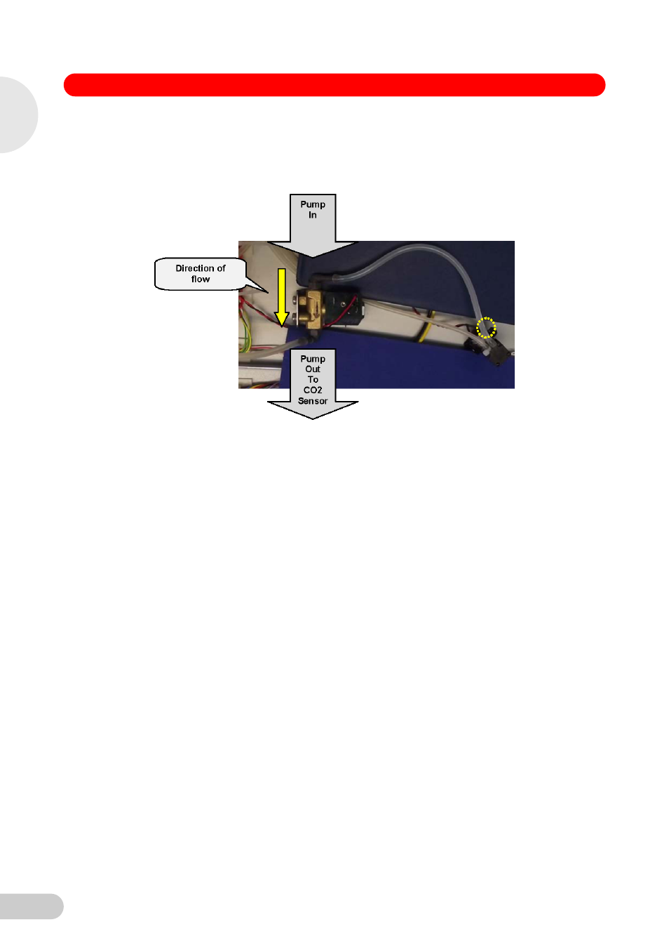
17. Disconnect the tube from the Auto-Zero Pump “Out” (see Pump diagram at bottom of page 7)
and connect to the “Pump Out to CO
2
Sensor” barb of the Solenoid Valve (as shown in the
image below). Using the new tubing supplied, cut a length and connect to the “Pump In” barb
of the Solenoid Valve shown in the image below.
NOTE: If the elbow becomes loose when fitting tube, it must be resealed and secured. If the
elbow becomes loose, the integrity of the CO
2
upgrade may be compromised.
Note: Air flow must follow the direction of flow arrows on Auto-Zero Pump and CO
2
Solenoid
Valve.
Air Flow: Hepa filter..Air In….Auto-Zero pump..Air In / Air Out…….CO
2
Solenoid Valve…..Air
In / Air Out…..CO
2
Sensor Assembly…Air In.
18. Connect the existing wiring harness to the CO
2
Sensor connecting block (as shown on top left
and right-hand image, page 15). Ensure you have stripped 7 mm of insulation from the
existing harness wires and twisted the strands before connecting them.
NOTE: Green on the existing harness connects to Brown on the new CO
2
Sensor assembly
harness.
1
Galaxy 170 R / 48 R 120 V / 230 V CO
2
Inc
ubators