Galaxy® co2 sensor setup — instructions – Eppendorf Galaxy Gas Analyzer User Manual
Page 26
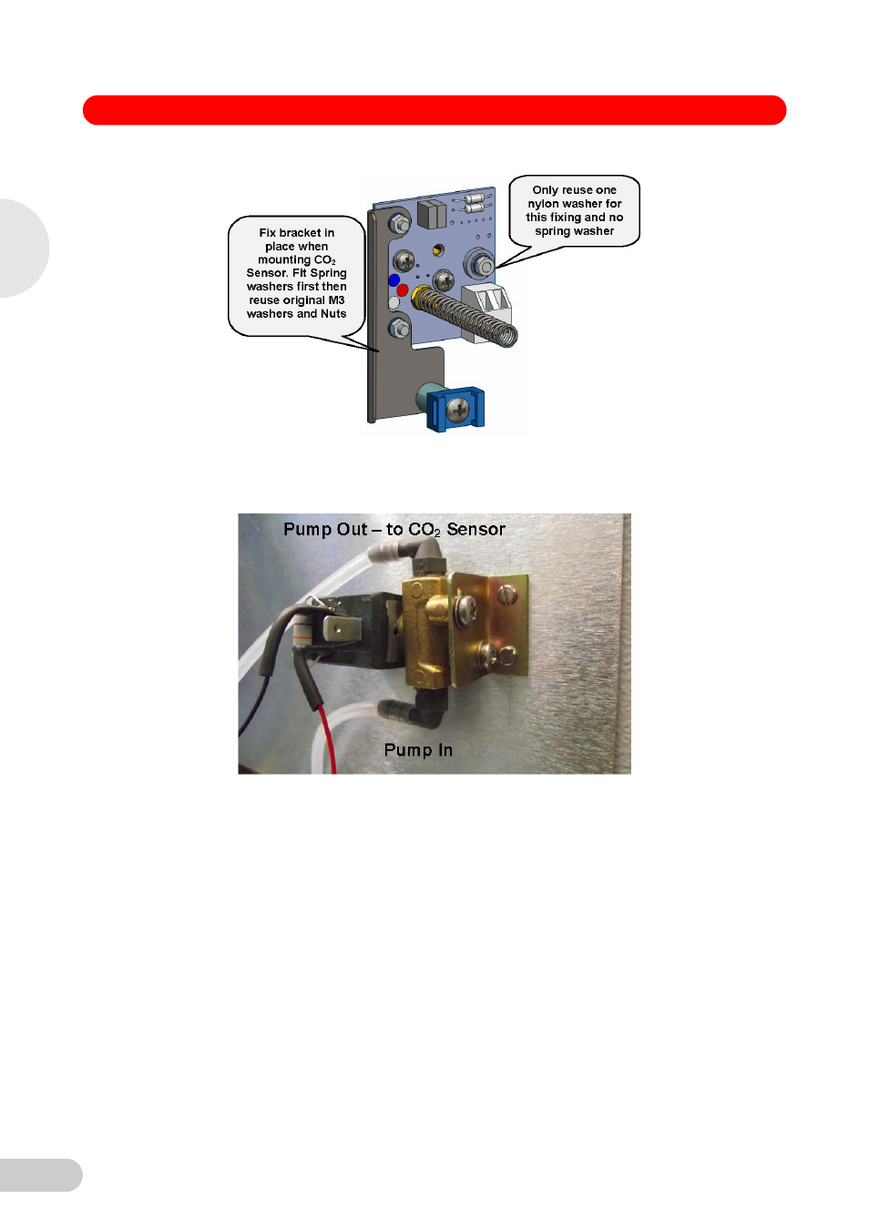
Galaxy® CO2 Sensor Setup — Instructions
26
19. Route the Auto-Zero inlet tubing from the CO
2
Sensor (pre fitted to the new Sensor) down
between the insulation and the back cover to the Solenoid Valve and connect the tubing to the
top barb of the Solenoid Valve as shown in the image below.
20. Route the tubing supplied from the new Auto-Zero Pump “Out” to the bottom barb of the
Solenoid Valve shown in the image above and reconnect the “Pump In – from Inlet filter”
tubing.to the other barb of the new Auto-Zero Pump.
NOTE: Air flow must follow the direction of flow arrows on Auto-Zero Pump and CO
2
Solenoid
Valve.
Air Flow: Hepa filter..Air In….Auto-Zero pump..Air In / Air Out…….CO
2
Solenoid Valve…..Air
In / Air Out…..CO
2
Sensor Assembly…Air In.
NOTE: If the elbow becomes loose when fitting tube, it must be resealed with elbow secured
in direction shown. If the elbow becomes loose, the integrity of the CO
2
upgrade may be
compromised
2
Galaxy 170 S 230 V / 120 V CO
2
In
cubators
- epMotion 96 (76 pages)
- epMotion 5070 (100 pages)
- epMotion 5075 (130 pages)
- Centrifuge 5427 R (64 pages)
- Centrifuge 5427 R (104 pages)
- White Paper 14 (8 pages)
- Rolling Cabinet (34 pages)
- Mastercycler nexus (142 pages)
- Mastercycler nexus (118 pages)
- Concentrator plus (New Design) (48 pages)
- Concentrator plus (43 pages)
- Easypet 3 (38 pages)
- Xplorer (74 pages)
- Xplorer Adjustment (26 pages)
- AF2200 Plate Reader (72 pages)
- AF2200 Plate Reader (78 pages)
- G0.5 µPlate (32 pages)
- BioSpectrometer basic (104 pages)
- BioSpectrometer kinetic (106 pages)
- BioSpectrometer fluorescence (102 pages)
- Micro Test Tubes (5 pages)
- Microplates (10 pages)
- PiezoXpert (34 pages)
- Eporator (38 pages)
- MiniSpin (20 pages)
- MiniSpin (25 pages)
- Centrifuge 5702 (32 pages)
- 5702 Centrifuge (27 pages)
- 5702 Centrifuge (32 pages)
- C5702 RH Centrifuge (32 pages)
- 5418 Centrifuge (80 pages)
- 5418 Centrifuge (48 pages)
- 5424 Centrifuge (44 pages)
- 5424 Centrifuge (71 pages)
- 5430 Centrifuge (88 pages)
- 5430 Centrifuge (130 pages)
- 5804 Centrifuge (95 pages)
- 5804 Centrifuge (127 pages)
- 5804 Centrifuge (129 pages)
- TransferMan4 r (102 pages)
- TransferMan4 m (96 pages)
- InjectMan 4 (100 pages)
- InjectMan NI 2 (60 pages)
- InjectMan NI 2 (16 pages)
- PatchMan NP 2 (53 pages)