Galaxy® co2 sensor setup — instructions – Eppendorf Galaxy Gas Analyzer User Manual
Page 21
21
Galaxy® CO2 Sensor Setup — Instructions
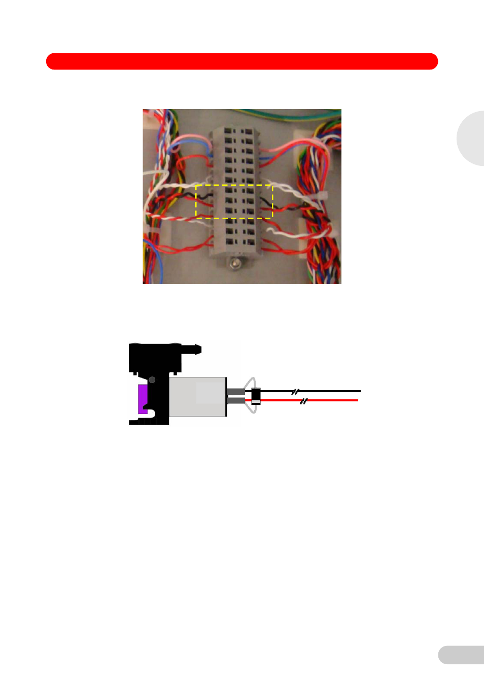
WAGO connecting block with Auto-Zero Pump connections highlighted
Fitting the new Parts
8. Fit the new Pump with Diode supplied in the Kit and cable zip tie the wiring down in the same
locations as the old pump. Trim the wires to length then strip and twist 7 mm for connecting
back into the WAGO connector block.
9. The PCB can now be positioned in the right-hand corner of the tray but it may be necessary
to relocate the 3 x Connectors for the Door Harness to clear room for the Auto-Zero Solenoid
Valve PCB/bracket (see blue arrows in image on following page). The Harness connectors
are cable zip tied to adhesive bases which are fixed down to the tray, there may also be other
cable zip ties and bases securing the wiring to the tray (see locations in dashed yellow circles
in image on following page.)
10. Cut all cable zip ties and relocate the connectors with the cable zip ties and bases provided in
the kit, leaving enough clearance for the Solenoid Check Valve PCB/bracket. After the Door
Harness connections have been moved the bracket mounting points will be visible.
2
Galax
y 170 S 230 V / 120 V CO
2
Incuba
to
rs