Galaxy® co2 sensor setup — instructions – Eppendorf Galaxy Gas Analyzer User Manual
Page 8
Galaxy® CO2 Sensor Setup — Instructions
8
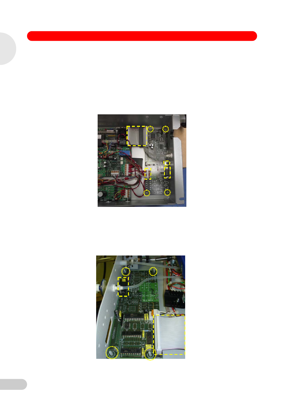
7. Existing Expansion PCB removal:
170 R – Using the diagram below with points highlighted in yellow:
1. Disconnect the 40 way Ribbon cable to Board 2 Expansion PCB.
2. Remove the 3 mm Nut securing the Earth tag to the Tray.
3. Unscrew the 2 x RS232 Hex head fixing posts.
4. Disconnect the wiring for the Live In and the Base Element Live Out as well as the wiring
for any other options fitted. Take note of locations if unsure as this will help to reconnect
the replacement Expansion PCB.
5. Remove the 4 x Pozidriv Head Securing Screws.
48 R – Using the diagram below with points highlighted in yellow:
1. Disconnect the 40 way Ribbon cable to Board 2 Expansion PCB.
2. Unscrew the 2 x RS232 Hex head fixing posts.
3. Disconnect the wiring for any options fitted. Take note of locations if unsure as this will
help to reconnect the replacement Expansion PCB.
4. Lift up carefully from the PCB Support Pillars.
1
Galaxy 170 R / 48 R 120 V / 230 V CO
2
Inc
ubators