Page 35, Swing carriage attachment on, Side tilt carriage attachment on – SkyTrak 6036 Operation Manual User Manual
Page 41: Figure 18c figure 18d
Page 35
6036/6036T
OA1101
OA1121
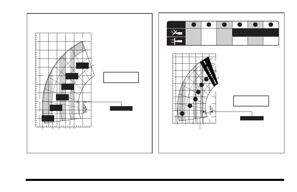
The capacity chart for the Side Tilt Carriage (Figure
18C) can be interpreted in the same way as the stan-
dard capacity chart. Refer to preceding example.
The capacity chart for the Swing Carriage (Figure 18D)
can be interpreted in the same way as the standard
capacity chart. Refer to preceding example.
60°
50°
40°
SIDE TILT CARRIAGE
ATTACHMENT ON
6036
4108232
LOAD CENTER
24 in (610 mm)
0 FT
(0 M)
0 FT
(0 M)
4
(1,2)
8
(2,4)
12
(3,7)
16
(4,9)
20
(6,1)
24
(7,3)
28
(8,5)
32
(9,8)
36
(11,0)
40
(12,2)
24
(7,3)
20
(6,1)
16
(4,9)
12
(3,7)
8
(2,4)
4
(1,2)
1500
LBS
680
KG
2500
LBS
1130
KG
3000
LBS
1360
KG
4000
LBS
1810
KG
6000
LBS
2720
KG
5000
LBS
2270
KG
D
C
B
A
22.8
(6,9)
18
(5,5)
15
(4,6)
10
(3,1)
8
(2,4)
0°
10°
20°
30°
70°
12
(3,7)
13.00 24 10 PLY TIRES
at 55 psi (379 kPa)
13.00 R 24 ONE STAR RADIALS
at 80 psi (551 kPa)
Hydrofill per operators manual
Load Ratings per
ASME B56.6-1987
DO NOT use this
attachment on 6036
equipped with 15-19.5 tires
13.00 24 10 PLY TIRES
at 55 psi (379 kPa)
13.00 R 24 ONE STAR RADIALS
at 80 psi (551 kPa)
Hydrofill per operators manual
Load Ratings per
ASME B56.6-1987
DO NOT use this
attachment on 6036
equipped with 15-19.5 tires
4107692
SWING CARRIAGE
ATTACHMENT ON
6036
1000 lbs
(454 kg)
2000 lbs
(910 kg)
3000 lbs
(1360 kg) 4000 lbs
(1810 kg)
5000 lbs
(2270 kg)
6000 lbs
(2720 kg)
1
2
3
4
5
6
4000 lbs (1810 kg)
LOAD
RANGE
70°
D
C
B
A
60°
50°
40°
30°
20°
0°
-8°
10°
24
(7,3)
23.2
(7,1)
4
(1,2)
0 ft
(0 m)
12
(3,7)
20
(6,1)
16
(4,9)
8
(2,4)
28
(8,5)
32
(9,8)
36
(11,0)
24
(7,3)
20
(6,1)
16
(4,9)
12
(3,7)
4
(1,2)
-4
-(1,2)
0 ft
(0 m)
8
(2,4)
18
(5,5)
13.5
(4,1)
11
(3,4)
9.5
(2,9)
7.5
(2,3)
2
3
4
5
6
1
LOAD CENTER
24 in (610 mm)
Figure 18C
Figure 18D