Installation instruc tio ns – Poison Spyder CJ ROCKBRAWLER REAR BUMPER WITH TIRE CARRIER User Manual
Page 4
INSTALLATION INSTRUC
TIO
NS
©2011 POISON SPYDER CUSTOMS, INC. • 951-849-5911 • WWW.POISONSPYDER.COM
Poison Spyder Customs • TJ-YJ-CJ ROCKBRAWLER REAR BUMPER
Page 4
20. Install the Latch Receiver into the latch
receiver housing on the bumper as shown in
Figure 11 using (2) 5/16-18 X 3/4 SS Button
Head Cap Screws with a drop of Loctite® 242
(blue) or equivalent thread lock compound
on the threads of each fastener. The rubber
bumpers at the top and bottom of the receiver
should taper (get narrower) toward the rear of
the latch receiver housing (toward the front of
the Jeep). Leave the two screws untightened
until completing the next step.
FIGURE 11
21. Install the Latch Pin into the Latch
Receiver, as shown in Figure 11, with a drop
of Loctite® 242 (blue) or equivalent thread
lock compound on the threads of the latch
pin. Tighten with a Torx T50 driver bit, then
tighten the two button head cap screws that
were installed in the previous step.
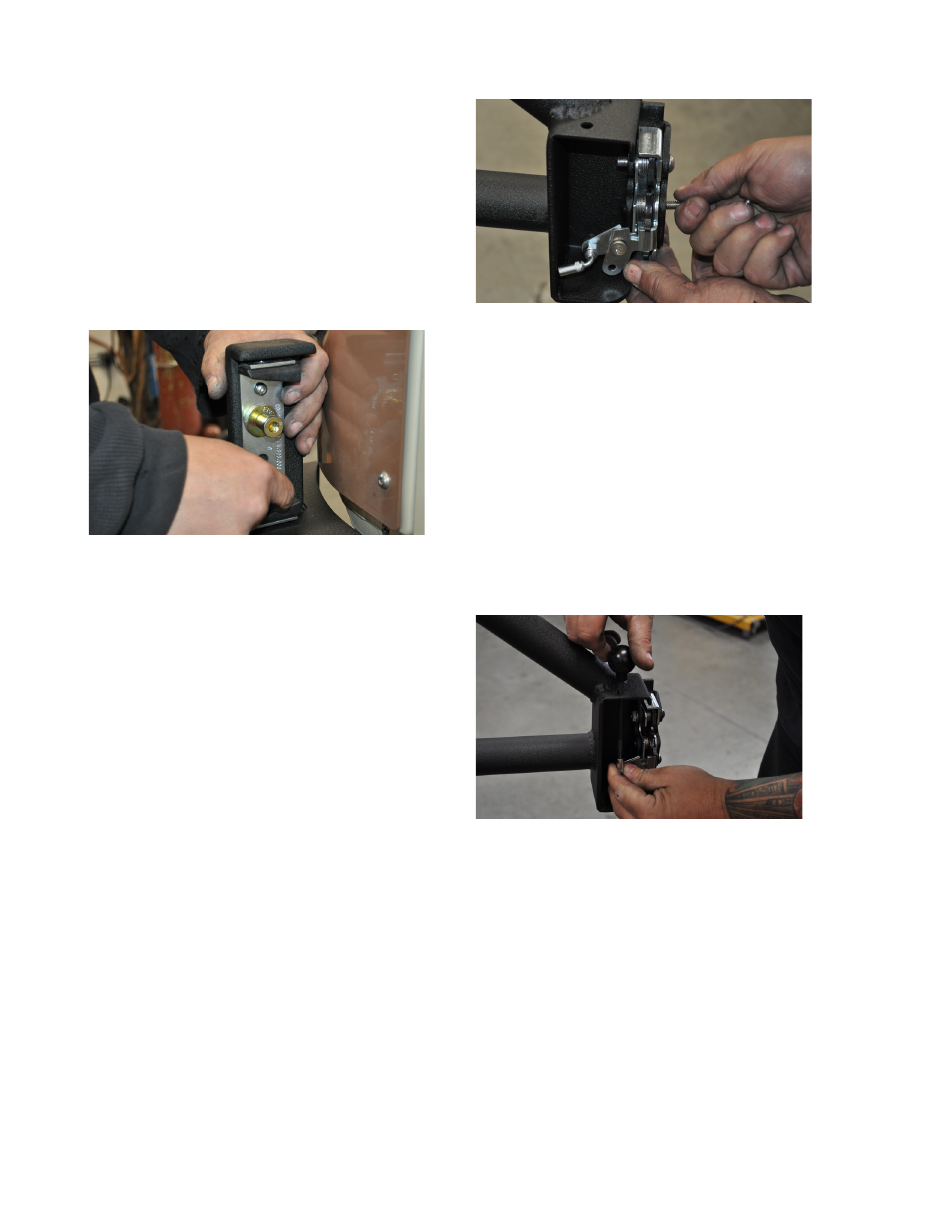
22. Install the Latch mechanism into the latch
mechanism housing on the tire carrier as
shown in Figure 12, using the (3) 5/16-18 X
1-1/2 SS Button Head Cap Screws and (3)
5/16-18 Nylon Insert Lock Nuts. The through-
holes in the latch mechanism will correspond
to the holes in the latch mechanism housing,
making its intended orientation obvious. Make
sure the button heads are to the outside, and
the lock nuts are on the inside. Snug these
fasteners at this time, but do not fully tighten
them until the final steps.
FIGURE 12
23. Install the Ball Joint Elbow onto the Latch
Mechanism actuator arm as shown in Figure
2, with a 1/4-20 Nylon Insert Lock Nut on the
back side of the threaded stud of the elbow.
24. Insert the Threaded Latch Rod through the
small hole in the top of the latch mechanism
housing and thread it into the threaded elbow
with a drop of Loctite® 242 (blue) or equivalent
thread lock compound on the threads.
25. Thread the Latch Knob onto the end of
the Threaded Latch Rod with a drop of
Loctite® 242 (blue) or equivalent thread lock
compound on the threads.
FIGURE 13
NOTE: If testing the alignment of the latch
components at this time, they may be significantly
vertically misaligned. We intentionally build
the Tire Carrier with “pre-load” so that once the
weight of the spare tire is on it, it will more closely
align. Do not worry about misalignment until after
the spare tire is mounted in the later steps.
26. Use three #10-32 X 3/4 SS button head cap
screws with #10-32 nylon insert lock nuts
to attach the Spyder Web Gusset Detail to
the gusset on the tire carrier. Use a drop of
Loctite® 242 (blue) or equivalent thread lock
compound on the threads of each fastener.