Installation notes - impeller, Installation notes – impeller, Caution – Hale 80FC User Manual
Page 96
❑ Corrective Maintenance
96
Pump Ends
p/n: 029-0020-61-0
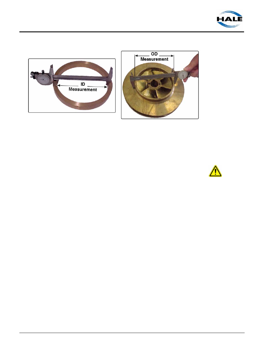
Figure 6a-6: Clearance Ring and Impeller ID / OD Measurement
The impeller hub diameter can be cut (turned down) and “undersized” clear-
ance rings can be ordered to compensate for a new impeller diameter. Contact
Customer Service at Hale Products at 610-825-6300.
CAUTION !
WHEN TURNING IMPELLERS TO FIT UNDERSIZED RINGS, CAUTION MUST BE
EXERCISED TO ENSURE THAT THE SEAL RING SURFACE RUNS TRUE WITH
THE BORE TO WITHIN 0.002” (0.051MM).
Installation Notes – Impeller
Follow the preceding steps in the reverse order, while paying attention to the fol-
lowing:
❑
Review heading 6a.1 “General Preparation” on page 85.
❑
Review heading 6a.1 “General Preparation” on page 85.
❑
Align the impeller to the keyway, then slide onto the pump shaft.
❑
For 30 FS series pumps - apply Loctite to the threads, then instal the 3/4”-
16 nut and washer and torque to approximately 104 ft.-lbs. (141 N-m)
❑
For all other pump models
●
Apply Loctite to the threads, then install the impeller nut and torque to 210
ft.-lbs. (285 N-m) minimum.
●
Continue tightening the impeller nut until the cotter pin can be installed to
lock the nut in place.
●
Install cotter pin and bend over the ends.