6b mechanical seal assembly, 6b.1 removing the seal, Figure 6b-1: typical mechanical seal assembly – Hale 80FC User Manual
Page 111: See section 6a
111
Mechanical Seal Replacement
Hale Products, Inc., March 2007, Rev-C
M e ch an ic al Se al Re p la ce me n t
❑
6b Mechanical Seal Assembly
IMPORTANT !
IF WATER LEAKAGE FROM THE DRAIN HOLE IN THE VOLUTE IS NOTICED, THE
IMPELLER MUST BE REMOVED AND THE MECHANICAL SEAL MUST BE
INSPECTED. (SEE FIGURE 6B-1: “TYPICAL MECHANICAL SEAL ASSEMBLY.”)
WHENEVER A MECHANICAL SEAL IS REMOVED, IT MUST BE REPLACED WITH A
“NEW” SEAL.
Before the mechanical seal can be replaced, the pump volute (pump body) and impel-
ler must be removed. Follow the instructions for removal and installation the volute and
impeller, based on your pump model, as detailed in the standard the Installation, Oper-
ation and Service Maintenance Manual provided with your pump.
6B.1
REMOVING THE SEAL
To expose the
mechanical seal, first
remove the:
❑
Pump suction
head, if included.
❑
Impeller - see
heading “Impeller”
on page 85.
1.
From within the
pump head, and
using two jaw-type
puller tools (hook-
type), spaced 180° apart, reach in and pry (pull) the seal ring from the pump
shaft.
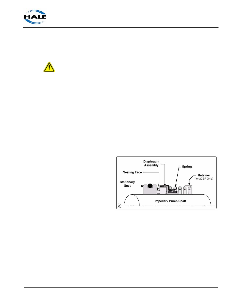
Note: On pump models CBP and 2CBP first remove the spring retainer. (See Figure
6b-1: “Typical Mechanical Seal Assembly.”)
2.
Place two hook-type tools or two small screw drivers, 180° apart, between
the diaphragm assembly and the stationary sealing face. Using steady,
gentle pressure, pry the diaphragm assembly from the shaft.
3.
Slide the short end of a 3/32” or 7/74” (2.5 mm - 3.0 mm) hex key between
the back side of the pump head and the pump shaft.
Figure 6b-1: Typical Mechanical Seal Assembly