Figure 2a-3: model “k” heat exchanger, P series relief valve system, Figure 2a-4: p series relief valve control – Hale 80FC User Manual
Page 39: Thermal relief valves (trv)
39
Section 2a: Accessories
Hale Products, Inc., May 2006, Rev-B
A cc es so r ie s / O p tio ns
❑
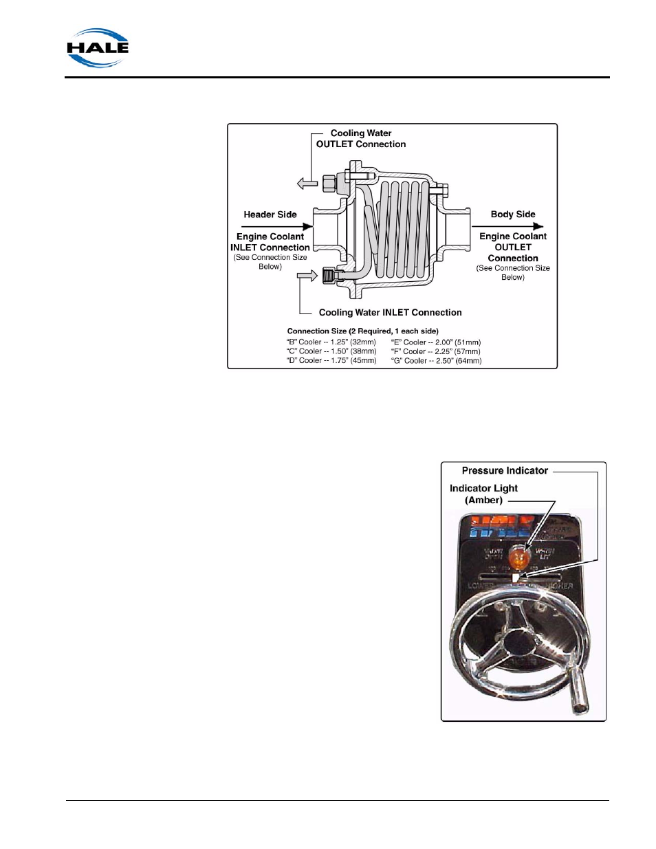
Figure 2a-3: Model “K” Heat Exchanger
P Series Relief Valve System
The P Series relief valve system is a
bronze, variable-pressure setting, relief
valve that prevents undue pressure per
the requirements of NFPA Standard
1901. An AMBER indicator light on the
operator control panel signals when the
valve is open. (See Figure 2a-4: “P
Series Relief Valve Control.”)
The P series relief valve system includes
a panel mounted control valve (PM) and
a relief valve (P25, P30 or P30V). Also
see Section 9, “Drawing Package” on
page 133.
Thermal Relief Valves (TRV)
Thermal Relief Valves (TRV) protect the
pump from overheating. (See Figure 2a-
5: “Thermal Relief Valve, TRV,” on page
40.)
Figure 2a-4: P Series Relief Valve
Control