Figure 2-12: typical pump and gearbox overview, Impeller, Figure 2-13: impeller operation – Hale 80FC User Manual
Page 33
33
Pump Ends
p/n: 029-0020-61-0
In tro d u ctio n
❑
This gradual increase in
size maintains a con-
stant average velocity
through the volute.
The volute is a single
piece, and must be
removed to service the
impeller, clearance rings,
and mechanical seal.
Removal of the volute
can often be accom-
plished without remov-
ing the pump and
gearbox assembly from
the apparatus.
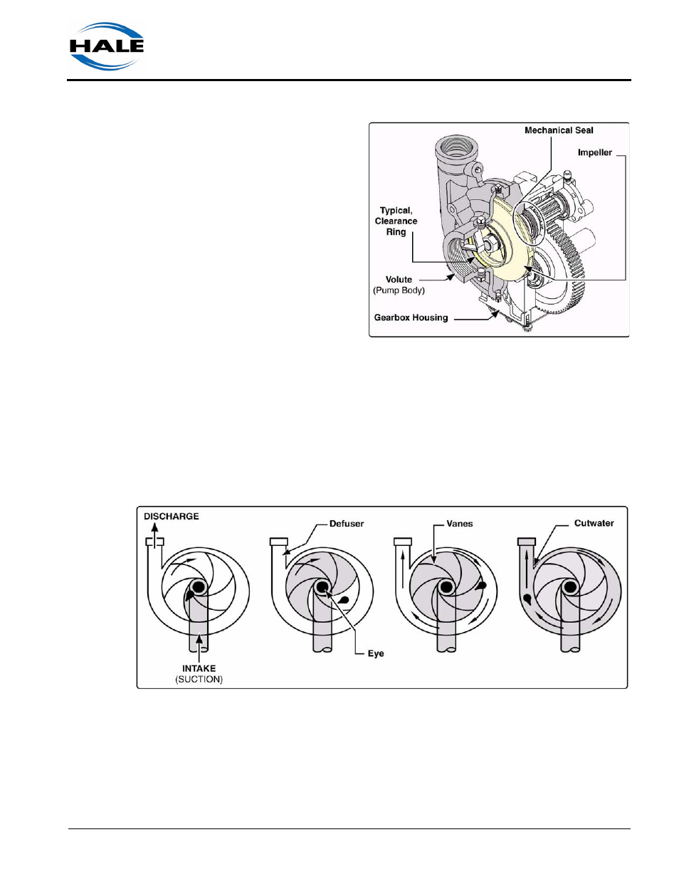
Impeller
The impeller provides velocity to the water. Water enters the rotating impel-
ler at the intake (or eye), and is confined by the shrouds and the vanes to
build pressure. The vanes guide water from the inlet to the discharge and
reduce the turbulence of the spinning water. (See Figure 2-13: “Impeller
Operation.”)
Figure 2-13: Impeller Operation
As water discharges from the impeller, it enters the volute (pump body).
The volute increases in size from the cutwater to its full capacity at the
volute throat. This gradual increase maintains a constant average velocity
through the volute. Figure 2-13: “Impeller Operation” traces a drop of water
from the intake of the impeller to the discharge outlet.
Figure 2-12: Typical Pump and Gearbox Overview