Oil seal, pump shaft, Figure 6a-2: oil seal, pump shaft – Hale 80FC User Manual
Page 89
89
Pump Ends
p/n: 029-0020-61-0
Co rr ec tive M ain te n an ce
❑
❑
Apply Loctite and install the 3/4”-16 washer and impeller nut and torque the
impeller nut to approximately 200 ft.-lbs. (271 N-m).
❑
Install the dowel pins (2) into the UPPER and LOWER pump body halves
before installing them.
❑
Apply Loctite to all screws and tighten in a criss-cross pattern to ensure an
EVEN seal. Refer to Table 6-1: “Typical Torque Values Chart” on page 79 for
recommended torque values, fastener size and material.
❑
Reconnect all cooling lines, primer lines, piping and tubing.
❑
Before returning apparatus to service, inspect system for leaks and proper
operation.
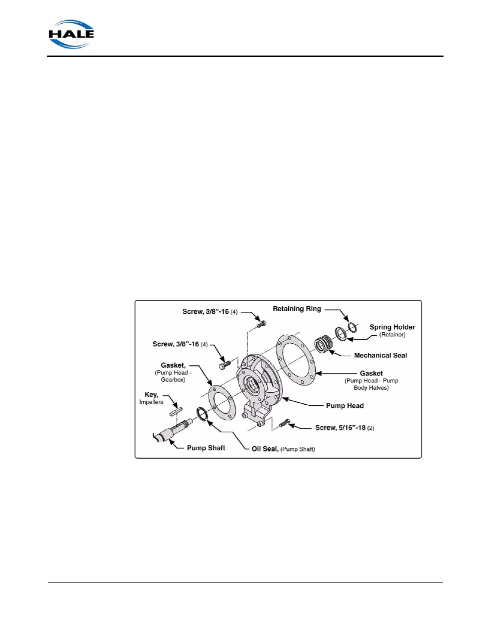
Oil Seal, Pump Shaft
To expose the pump shaft oil seal you must remove the bearing housing assem-
bly, pump body, impellers (2) and the mechanical seal, as discussed in the pre-
ceding sections. Also see Figure 6a-2: “Oil Seal, Pump Shaft.”
Figure 6a-2: Oil Seal, Pump Shaft
1.
Remove the pump head assembly - four (4) 3/8”-16 and two (2) 5/16”-18
screws securing the assembly to the gearbox.
2.
Slide the pump head from the shaft being careful not to damage the shaft
surfaces. Place the assembly on a suitable work area.