Figure 6a-4: typical pump disassembly overview – Hale 80FC User Manual
Page 92
❑ Corrective Maintenance
92
Pump Ends
p/n: 029-0020-61-0
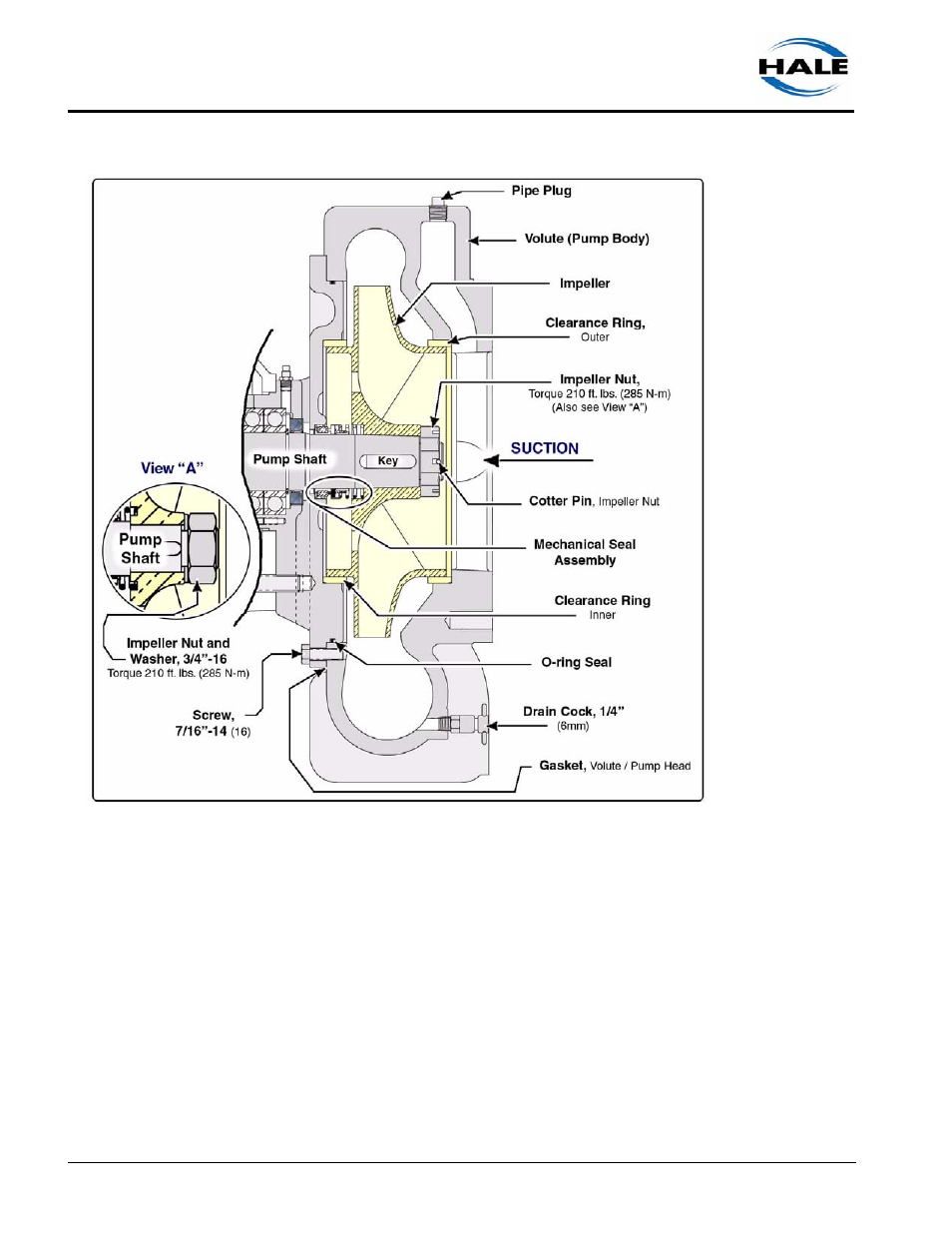
Figure 6a-4: Typical Pump Disassembly Overview
2.
Remove the suction flange (if installed) - see heading “Suction Flange” on
page 90.
3.
Disconnect the water line compression fittings and the gearbox water cool-
ing lines from the volute.
4.
Also disconnect primer lines, if included.
5.
Volutes are mounted for various pump discharge positions. Note the dis-
charge position of your pump before disassembly, then match-mark the
volute and pump head to assure proper alignment during reassembly.
6.
Remove the screws securing the volute to the pump head: