Figure 2a-9: automatic pump shift overview, Figure 2a-10: pump shift control valve – Hale 80FC User Manual
Page 43
43
Section 2a: Accessories
Hale Products, Inc., May 2006, Rev-B
A cc es so r ie s / O p tio ns
❑
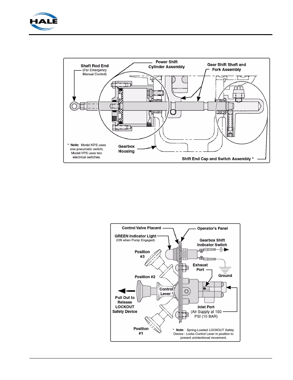
Figure 2a-9: Automatic Pump Shift Overview
It uses available apparatus vacuum or air pressure for power and is acti-
vated by an in-cab pump shift control valve. (See Figure 2a-10: “Pump Shift
Control Valve.”) The system includes a three-position pump shift control
valve assembly and indicator lights (GREEN), mounted in the operator’s
cab and on the operator’s panel.
Figure 2a-10: Pump Shift Control Valve