Grande, Medio - grande, Fr es – Vollrath GRANDE In-Chamber Vacuum Pack Machines User Manual
Page 41: Es en es fr
41
VACUUM PACKING MACHINE
CONDITIONNEUSE SOUS VIDE
MAQUINA DE VACÍO
Operating and service manual / Mode d’emploi et d’entretien
Manual de uso y mantenimiento / Ed. 01 - 2011
REV. 00 - Cod.: 1500386
FR
ES
MEDIO - GRANDE
PF1
PF2
•
•
•
PF4
•
PF5
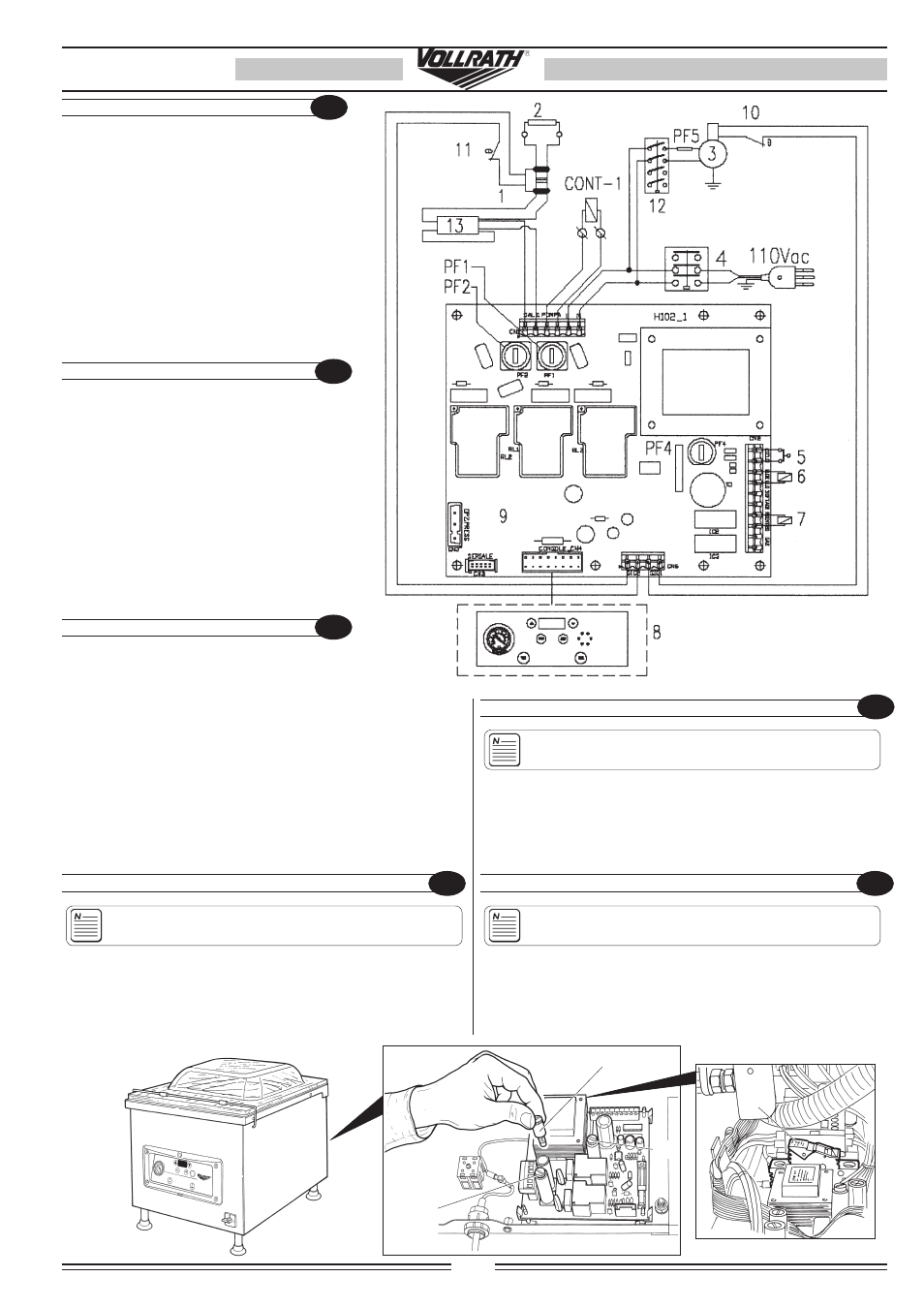
7.4.5
WIRING DIAGRAMS
1 Sealing Transformer
2 Sealing bar
3 Vacuum pump
4 Main switch
PF1 Pump fuse F1A 6,3X32
PF2 Sealing fuse T5A 6,3X32
PF4 Power board fuse F4A 5X20
PF5 Fusible 20A 10,3X38
5 Working cycle start
6 Sealing bar buffer valve
7 Chamber valve
8 Digital comand board
9 Power board type H102_1
10 Pump motor thermal protector
11 Sealing Transformer thermal protector
12 Pump electromagnetic switch
13 Timer
7.4.5
SCHÉMAS ÉLECTRIQUES
1 Transformateur de soudage
2 Barre soudante
3 Pompe à vide
4 Interrupteur général
PF1 Fusible pour pompe 6.3/8/10A
PF2 Fusible de soudage 2.5-8/2.5-10A
PF4 Fusible pour carte puissance 4A
PF5 Fusible 10,3x38 20A
5 Lancement du cycle de travail
6 Valve du tampon sous barre
7 Valve de retour d’air en chambre vide
8 Carte de commande numérique
9 Carte de puissance H102_1
10 Protecteur thermique moteur
11 Protecteur thermique du transformateur de soudage
12 Bobine télérupteur pompe 110V
13 Temporisateur
EN
GRANDE
FR
AVERTISSEMENT : Cette procédure doit être effectuée par
du personnel qualifié.
1) Désinsérer la fiche du réseau.
2) Enlever le panneau arrière et extraire la capsule porte-fusible en la
tournant dans le sens inverse des aiguilles d’une montre d’environ
un demitour et remplacer le fusible brûlé avec un fusible de mêmes
caractéristiques (voir tableau données techniques page 15).
REMPLACEMENT FUSIBLES
SUSTITUCIÓN FUSIBLES
DVERTENCIA. Este procedimiento debe ser ejecutado por
personal cualificado.
1) Extraer el enchufe respecto de la toma eléctrica.
2) Levantar el panel trasero y extraer la cápsula portafusible, girándola para
ello en sentido antihorario en la medida aproximada de media vuelta, y
sustituir el fusible quemado con otro de iguales características (véase
tabla de datos técnicos, pág. 15).
REPLACING FUSES
WARNING: This operation must be performed only by qua-
lified personnel.
1) Disconnect the plug from the main socket.
2) Remove the rear panel and remove the fusebox capsule by rotating it
anticlockwise through half a turn and replace the burnt fuse with a new
fuse having identical features (See Technical Data Table page 15).
7.4.5
ESQUEMAS ELÉCTRICOS
1 Transformador de soldadura
2 Barra soldante
3 Bomba de vacío
4 interruptor general
PF1 Fusible para bomba 6.3/8/10A
PF2 Fusible de soldadura 2.5-8/2.5-10A
PF4 Fusible para tarjeta de potencia 4A
PF5 Fusible 10,3x38 20A
5 Puesta en marcha del ciclo de trabajo
6
Válvula cojinete bajo barra
7 Válvula de reingreso de aire en la cámara
de vacío
8 Placa de comandos digitales
9 Placa de potencia H102_1
10 protector térmico del transformador de soldadura
11 Protector térmico del transformador de soldadura
12 Bobina telerruptor bonba 110V
13 Temporizador
ES
EN
ES
FR