Medio - grande, Ed a – Vollrath GRANDE In-Chamber Vacuum Pack Machines User Manual
Page 18
18
VACUUM PACKING MACHINE
CONDITIONNEUSE SOUS VIDE
MAQUINA DE VACÍO
Operating and service manual / Mode d’emploi et d’entretien
Manual de uso y mantenimiento / Ed. 01 - 2011
REV. 00 - Cod.: 1500386
EN
MEDIO - GRANDE
Fig. 1
5.
INSTALLATION
5.1
APPLIANCE DESCRIPTION
The
Series vacuum packaging machines are meant for packing dry and/or cured products, thanks to the operating principle based on creation of
vacuum inside a chamber (or tray), inside which the product in a special bag or rigid container is placed.
If provided with a special valve, the machine can also be used for vacuum-packaging of products in the above-mentioned rigid containers outside the
chamber. As explained in detail in the “USING THE APPLIANCE” Chapter, some models can be used for creating a vacuum in special “channelled”
bags outside the vacuum chamber, thereby making it possible to pack products larger than the vacuum chamber dimensions.
The work cycles (vacuum, bag sealing, devacumation and opening the cover) are carried out automatically in sequence.
In the versions with digital controls, the functions can be programmed for up to a maximum of 10 programs.
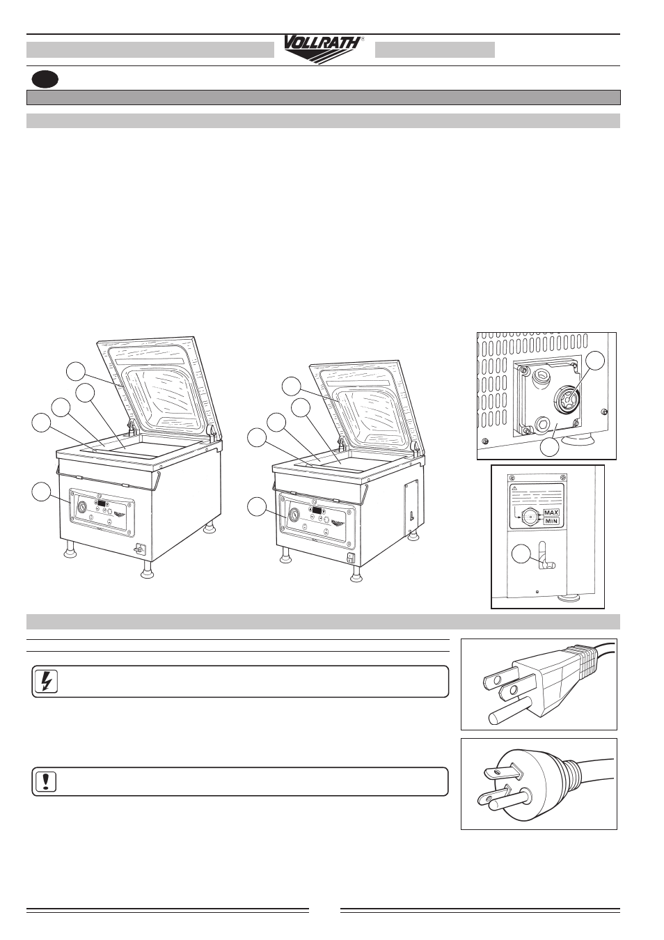
The machines basically consist of the following parts:
• a stainless steel chamber (vacuum chamber)
(A) inside which vacuum is created and bags are sealed by means of sealing bars (B); it is fitted
with
a transparent plexiglas cover
(C) that can be opened, and through which the operating phases can be observed. The depth
inside the chamber may be changed using plastic insertion plates
(D) supplied with the machine;
• a stainless steel casing
(E) with the control panel and main switch located on the front, and the back is closed by a stainless steel panel.
• a high-performance vacuum pump
(F) lubricated in recirculation with glass window (G) for checking the oil level;
• an air evacuation system consisting of unions, pipes and solenoid valves which connects the vacuum chamber to the pump and the system
adjustment and/or control organs;
• an electrical system which includes the power board with fusebox, control and connections board. All the functions are controlled by a
microprocessor.
INSTALLATION
C
•
•
E
D
A
•
•
•
B
C
•
•
E
D
A
•
•
•
B
•
G
•
G
F
•
5.2
SUPPLY VOLTAGE
5.2.1
115V SINGLE-FASE POWER SUPPLY
ELECTRIC HAZARD! Before making the connection, always check to make sure the
electrical features of the system in the installation area are suitable.
To reduce the risk of electric shock, this product has a polarized plug (one blade is wider than other). This
plug is intended to fit in a polarized outlet only one way.
When the plug does not fit fully in the outlet, reverse the plug. When it still does not fit, contact a qualified
electrician to install the proper outlet. Do not change the plug in any way.
CAUTION: To provide continued protection against risk of electric shock, connect
to properly grounded outlets only.