Figure 16. peak detect & limiter, 7 line-level outputs and filtering, Figure 16.peak detect & limiter – Cirrus Logic CS42L51 User Manual
Page 37: Cs42l51
DS679F1
37
CS42L51
4.4.7
Line-Level Outputs and Filtering
The CODEC contains on-chip buffer amplifiers capable of producing line level single-ended outputs on
AOUTA and AOUTB. These amplifiers are ground centered and do not have any DC offset. A load stabi-
lizer circuit, shown in the
“Typical Connection Diagram (Software Mode)” on page 10
and the
Connection Diagram (Hardware Mode)” on page 11
, is required on the analog outputs. This allows the
DAC amplifiers to drive line or headphone outputs.
Also shown in the Typical Connection diagrams is the recommended passive output filter to support high-
er impedances such as those found on the inputs to operational amplifiers. “Rext”, shown in the typical
connection diagrams, is the input impedance of the receiving device.
The invert and digital gain controls may be used to provide phase and/or amplitude compensation for an
external filter.
The delta-sigma conversion process produces high frequency noise beyond the audio passband, most of
which is removed by the on-chip analog filters. The remaining out-of-band noise can be attenuated using
an off-chip low pass filter.
Software
Controls:
“DAC Output Control (Address 08h)” on page 57
“AOUTx Volume Control: AOUTA (Address 16h)
& AOUTB (Address 17h)” on page 66
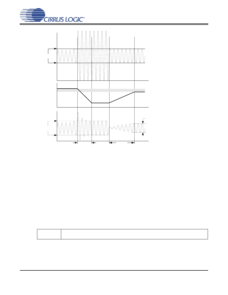
MAX[2:0]
Output
(after Limiter)
Input
RRATE[5:0]
ARATE[5:0]
Volume
Limiter
CUSH[2:0]
ATTACK/RELEASE SOUND
CUSHION
MAX[2:0]
AOUTx_VOL[7:0] volume
control should NOT be
adjusted manually when
Limiter is enabled.
Figure 16. Peak Detect & Limiter